Particle beam irradiation system and operating method

a particle beam and irradiation system technology, applied in radiation therapy, x-ray/gamma-ray/particle irradiation therapy, therapy, etc., can solve the problems of obstructing the shortening of the treatment time required, obstructing the shortening of the treatment time, and the operation cannot be directly shifted from extraction energy control, so as to improve the dose rate and improve the effect of treatment time and dose ra

Active Publication Date: 2016-04-12
HITACHI LTD
View PDF14 Cites 5 Cited by
  • Summary
  • Abstract
  • Description
  • Claims
  • Application Information

AI Technical Summary

Benefits of technology

[0031]According to the present invention, in the multi-energy extraction control operation that realizes change control of an extraction beam energy in a synchrotron in a short time, when ion beam irradiation is halted, updating of an operating cycle is conducted in a short time and a dose rate is improved so that the treatment time can be reduced.
[0032]In addition, according to the present invention, beam irradiation in a desired energy range is conducted at a short operating cycle and a dose rate is improved so that the treatment time can be reduced.

Problems solved by technology

The repetition of ion beam energy change control, as in the scanning irradiation method, poses a problem that since the synchrotron requires the updating of its operating cycle, an energy change tends to be a time-consuming task.
This shifting time from extraction energy control to deceleration control is one of the causative factors lowering the dose rate and obstructing the shortening of the treatment time required.
Likewise, the operation cannot be directly shifted from extraction energy control to deceleration control if trouble with a constituent element or device of the particle beam irradiation apparatus results in the ion beam irradiation being halted.
If the integrated set of operating control data covering all energy levels available for the irradiation with the synchrotron is applied as the operating control data for the synchrotron, this leads to generating a wasteful time not contributing to beam irradiation.
This tendency keeps beam irradiation in a desired energy range from being conducted at a short operating cycle, and is another causative factor lowering the dose rate and obstructing the shortening of the treatment time.

Method used


Image

  • Particle beam irradiation system and operating method
  • Particle beam irradiation system and operating method
  • Particle beam irradiation system and operating method

Examples


first embodiment

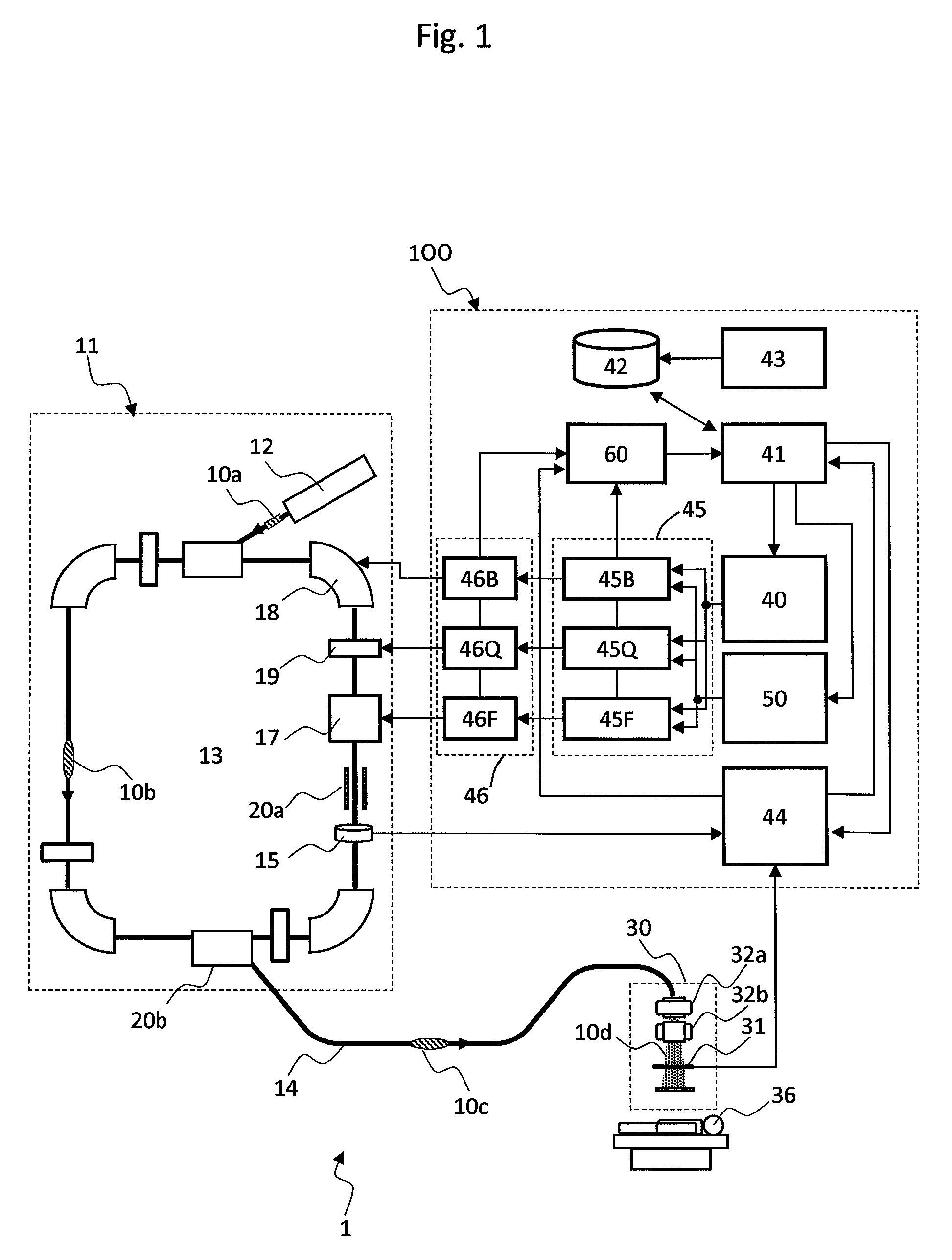
[0049]FIG. 1 is a diagram showing a configuration of a particle beam irradiation system according to a first embodiment of the present invention.

[0050]As shown in FIG. 1, the particle beam irradiation system 1 according to the present embodiment includes an ion beam generator 11, a beam transport apparatus 14, and an irradiation field forming apparatus (a charged-particle beam irradiation apparatus, hereinafter, referred to simply as the irradiation apparatus) 30. The beam transport apparatus 14 provides communication between the ion beam generator 11 and the irradiation apparatus 30 placed inside a treatment room.

[0051]The ion beam generator 11 includes an ion source (not shown), a pre-accelerator 12, and a synchrotron 13. The ion source is connected to the pre-accelerator 12, and the pre-accelerator 12 is connected to the synchrotron 13. The pre-accelerator 12 accelerates an ion beam 10, which has been generated by the ion source, to an energy level at which the ion beam can be in...

second embodiment

[0101]A second embodiment of the present invention is described below using FIGS. 9 to 13A and 13B.

[0102]First, a control data structure for the multi-energy extraction operation characterizing the present embodiment, and an operation sequence using the control data are described below using FIGS. 9 to 13A and 13B.

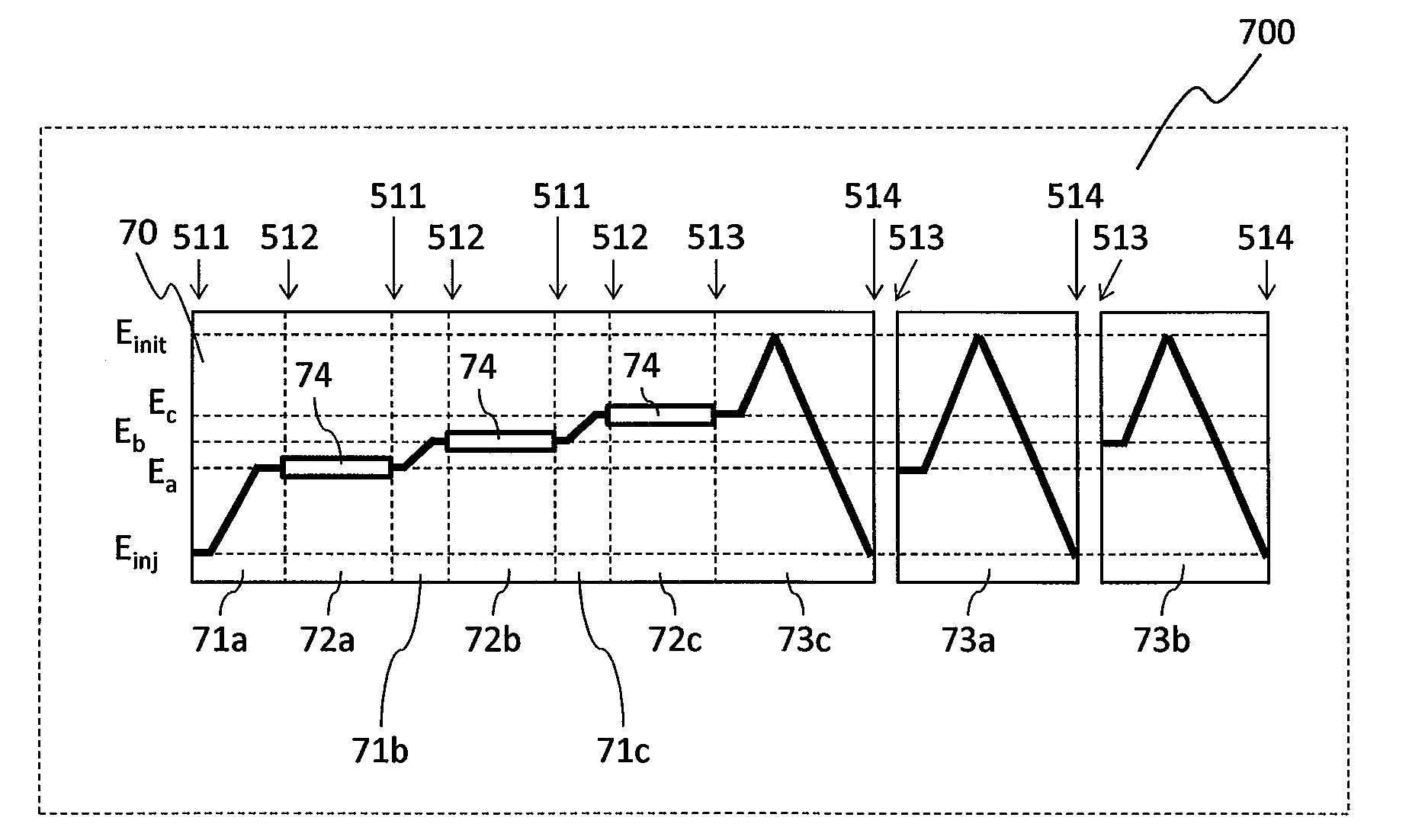
[0103]FIG. 9 is a diagram that shows composition of operating control data relating to the devices constituting the synchrotron, the diagram also showing the excitation current of the bending magnets 18 as a typical example of the operating control data relating to the devices of the synchrotron. In actuality, as shown in Non-Patent Document 2, data of the number of levels corresponding to the number of energy levels of the beams to be irradiated is provided, but the data described in the present embodiment is of three levels. In addition, while the operating control data that gives rise to sequential beam irradiation from lower energy levels to higher ones is shown in the...


PUM


Abstract

A particle beam irradiation system having a multi-energy extraction control operation that controls the extraction beam energy in a synchrotron within a short time, such that when the ion beam irradiation is halted, an operating cycle is updated within a short time and a dose rate is improved. To this end, operating control data for each of the devices constituting the synchrotron is constructed by multi-energy extraction control pattern data for controlling extraction of beams of a plurality of energy levels at one operating cycle, and a plurality of sets of deceleration control data that correspond to the extraction control of the beam of the plurality of energy levels. The devices are controlled by using the operating control data.

Description

BACKGROUND OF THE INVENTION[0001]The present invention relates to particle beam irradiation systems suitable for particle beam therapy using such a charged particle beam (ion beam) as of protons or heavy ions. More particularly, the invention is directed to a particle beam irradiation system configured to achieve beam energy change control and operating cycle update within a short time, and to a method for operating the system.[0002]Particle beam therapy, a treatment performed upon the cancer in a patient by irradiating the affected region with such an ion beam as of protons or heavy ions, is known as radiation therapy for cancer. Useable methods for ion beam irradiation include such a scanning irradiation method that is disclosed in REVIEW OF SCIENTIFIC INSTRUMENTS, VOLUME 64, NUMBER 8 (AUGUST 1993), pp. 2074-2093 (hereinafter referred to as Non-Patent Document 1).[0003]In addition, examples of a control method that realizes the beam energy change control required in a scanning irr...

Claims


Application Information

Patent Timeline
Patent Type & Authority Patents(United States)
IPC IPC(8): A61N5/10
CPCA61N5/1048A61N5/1077A61N2005/1087
Inventor NISHIUCHI, HIDEAKIUMEZAWA, MASUMINOMURA, TAKUYATOTAKE, SATOSHITOBINAGA, KOJIIMAGAWA, TOMOHISAYOSHIURA, SEIJITAKEDA, MOEMI
Owner HITACHI LTD
Why Eureka
Try Eureka