

Pneumatic transport system
a technology of pneumatic transport and pneumatic components, applied in the direction of conveying, material analysis, transportation and packaging, etc., can solve the problems of system trouble, item is subject to quite a shock and rough handling, and cannot be sent in a single instant succession, so as to achieve gentle reception, high speed, and certain flexibility
- Summary
- Abstract
- Description
- Claims
- Application Information
AI Technical Summary
Benefits of technology
Problems solved by technology
Method used
Image

Examples
Embodiment Construction
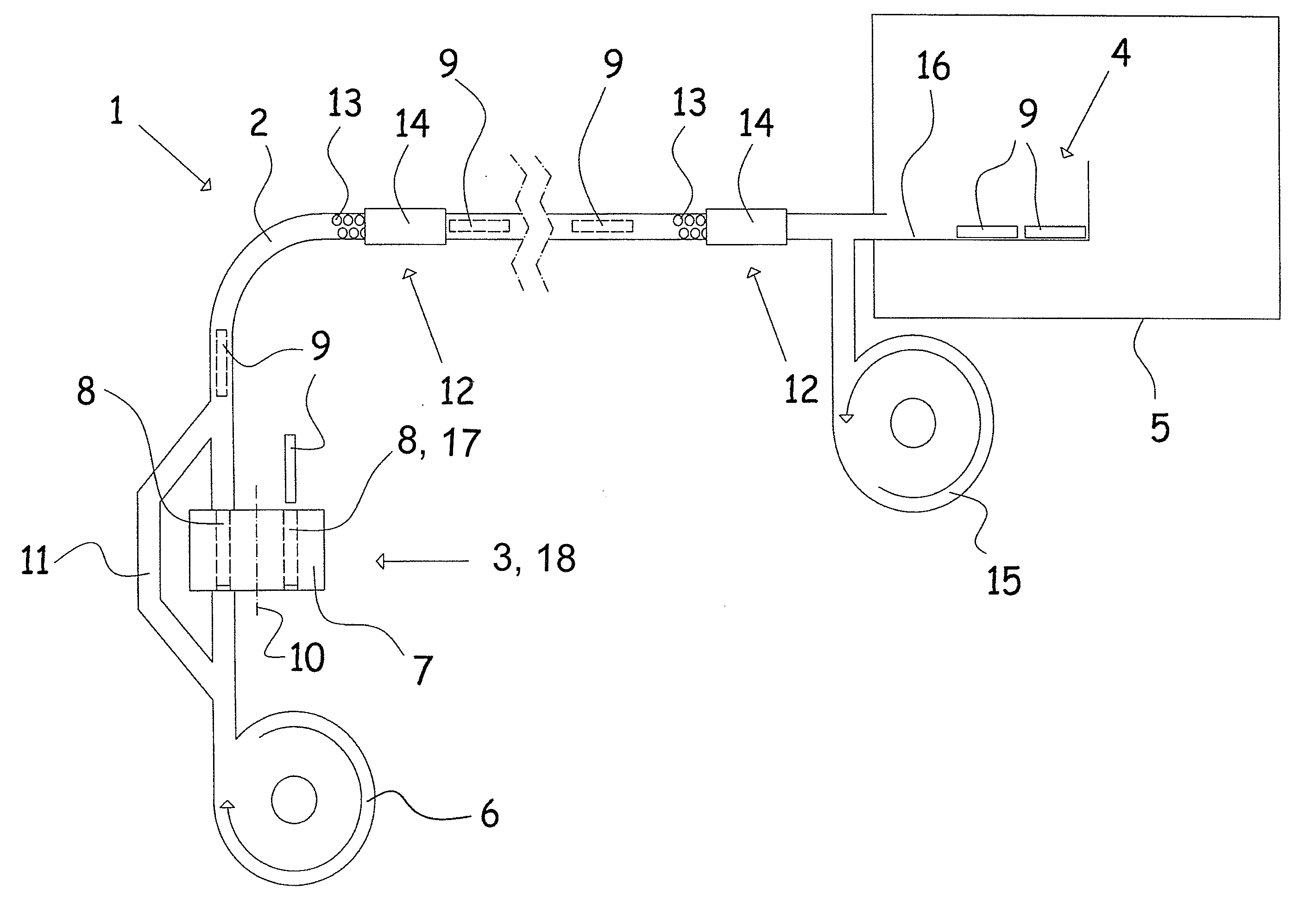
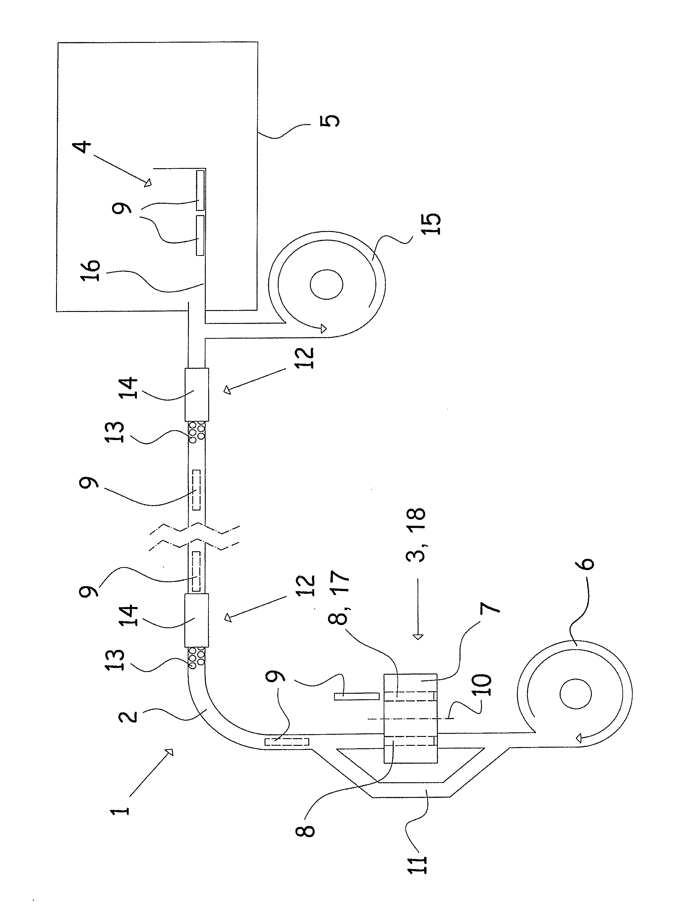
[0011]As indicated above, the invention concerns a conveying system where items via an airflow in a tube connection are conveyed in the direction of the airflow. A feature of a conveying system according to the invention is that the tube connection has an inner cross-sectional area, preferably a circular cross-sectional area, of a size greater than the largest cross-sectional area of an elongated item measured transversely of the longitudinal direction of the item, and which preferably is provided with at least twice the cross-sectional area compared with the largest cross-sectional area of the item, where the items have a length which is greater than the largest inner cross-dimension / diameter / diagonal. By such a solution it is possible to convey an item in the tube connection if there is an excess of air with a relatively small overpressure. By conducting a large amount of air through the tube system, the air may lift and convey the item over distances of several hundred meters. At...
PUM
 Abstract
Description
Claims
Application Information