
Alignment method of alignment film

a technology of alignment film and alignment method, which is applied in the field of alignment film alignment method, can solve the problems of unfavorable control of cloth hair quality, unfavorable uniform rubbing, and influence of alignment effect, so as to improve the stability of alignment, facilitate handling, and promote the effect of alignmen

Active Publication Date: 2016-04-12
TCL CHINA STAR OPTOELECTRONICS TECH CO LTD
View PDF5 Cites 0 Cited by
  • Summary
  • Abstract
  • Description
  • Claims
  • Application Information

AI Technical Summary

Benefits of technology

[0008]An objective of the present invention is to provide an alignment method of an alignment film which is easy to handle and capable of preventing the non-uniform rubbing issue existing in the alignment method according to prior art to raise the stability of the alignment and promote the effect of the alignment.
[0021]The benefits of the present invention are: according to the alignment method of the alignment film provided by the present invention, by implementing laser engraving to the alignment film to form a plurality of micro trenches which are directionally consistent for realizing the alignment. The method is easy to handle and capable of preventing the non-uniform rubbing issue existing in the alignment method according to prior art to raise the stability of the alignment and promote the effect of the alignment.

Problems solved by technology

However, no efficient method is proposed to control the quality of the cloth hairs for now.
Meanwhile, if the hairy roller is not flattening, the pressing degree to the PI alignment film cannot be precisely controlled which can cause the non uniform rubbing and influence the effect of the alignment, either.

Method used


Image

  • Alignment method of alignment film
  • Alignment method of alignment film
  • Alignment method of alignment film

Examples


Embodiment Construction

[0028]In order to better understand the characteristics and technical aspect of the invention, please refer to the following detailed description of the present invention is concerned with the diagrams.

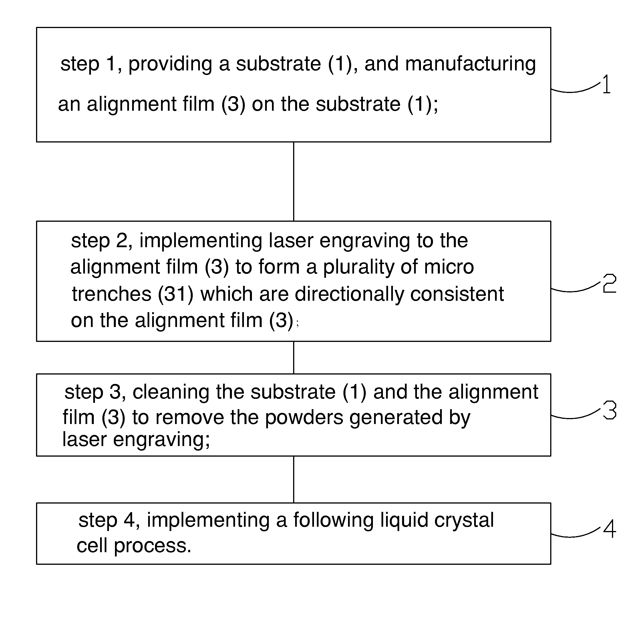
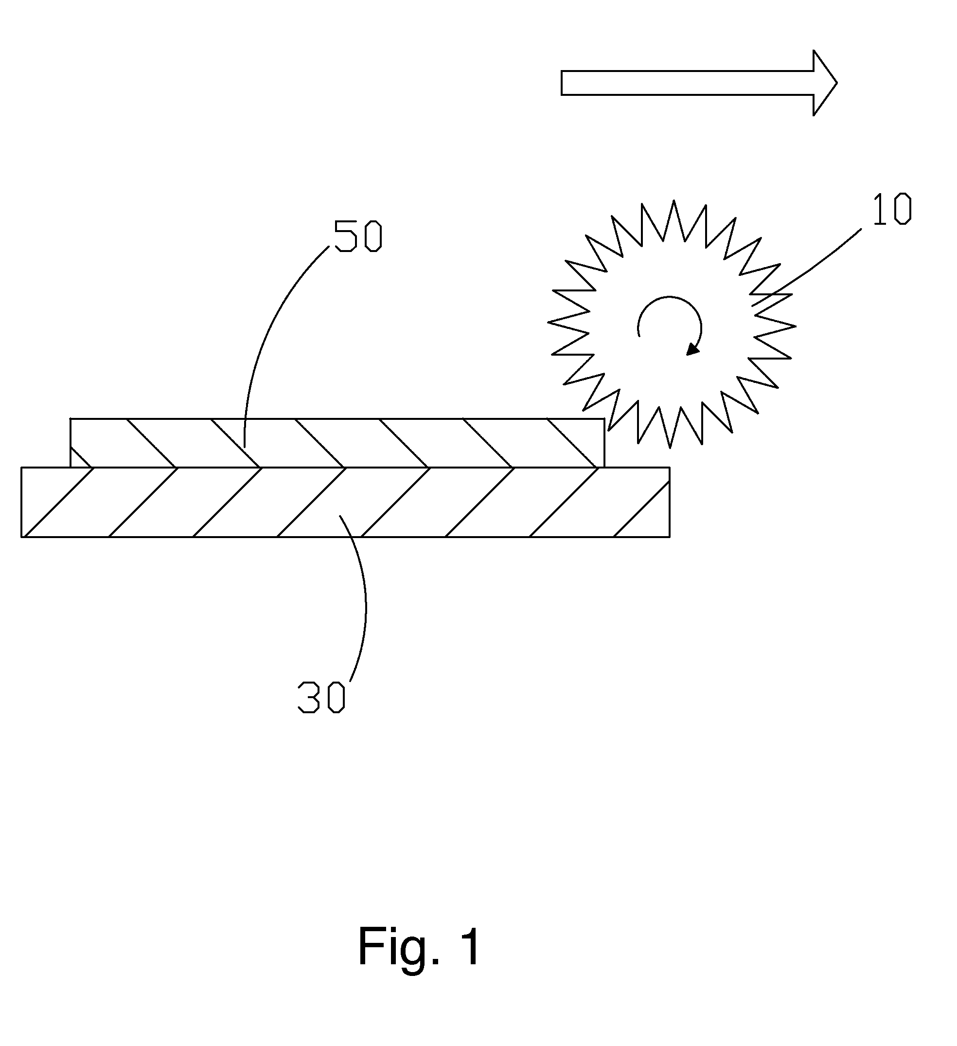
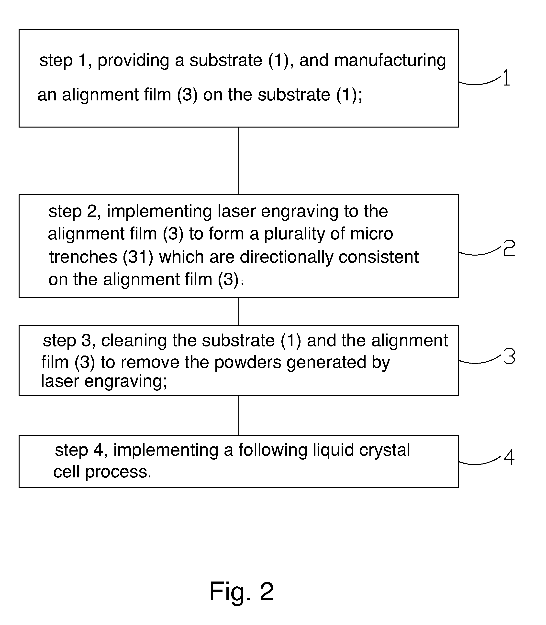
[0029]Please refer from FIG. 2 to FIG. 4. The present invention provides an alignment method of an alignment film, comprising steps of:

[0030]step 1, as shown in FIG. 3, providing a substrate 1, and manufacturing an alignment film 3 on the substrate 1.

[0031]Specifically, the substrate 1 is a TFT substrate or a CF substrate which the array process is accomplished.

[0032]Preferably, the alignment film 3 is a PI alignment film. The main component of the PI alignment film is Polyimide (PI). The procedure of manufacturing the alignment film 3 is to coat an alignment film basic solution on the substrate 1 and implementing a solidifying process to solidify the alignment film basic solution to ultimately form the alignment film 3.

[0033]step 2, as shown in FIG. 4, implementing laser engraving to...


PUM

PropertyMeasurementUnit
thicknessesaaaaaaaaaa
polar angleaaaaaaaaaa
pretilt angleaaaaaaaaaa

Abstract

An alignment method of an alignment film is provided, including: providing a substrate and manufacturing an alignment film on the substrate; implementing laser engraving to the alignment film to form a plurality of micro trenches which are directionally consistent on the alignment film; cleaning the substrate and the alignment film to remove the powders generated by laser engraving; and implementing a following liquid crystal cell process. The method is easy to handle and is capable of preventing the non-uniform rubbing issue existing in the alignment method according to prior art to raise the stability of the alignment and promote the effect of the alignment.

Description

FIELD OF THE INVENTION[0001]The present invention relates to a display technology field, and more particularly to an alignment method of an alignment film.BACKGROUND OF THE INVENTION[0002]Generally, a liquid crystal display panel mainly comprises a Thin Film Transistor Array Substrate (TFT Array Substrate), a Color Filter (CF) substrate and a Liquid Crystal Layer located between the two substrates. The working principle is that the light of backlight module is reflected to generate images by applying driving voltages to the two glass substrate for controlling the rotations of the liquid crystal molecules in the liquid crystal layer.[0003]To obtain more regular alignment of the liquid crystal molecules, Polyimide (PI) alignment films which have been processed with alignment treatment are arranged at sides of the Thin Film Transistor Array Substrate and Color Filter substrate close to the liquid crystal layer. In the PI alignment film processed with alignment treatment, acting forces ...

Claims


Application Information

Patent Timeline
Patent Type & Authority Patents(United States)
IPC IPC(8): H01L27/12G02F1/1337H01L21/02
CPCG02F1/13378G02F1/133723H01L21/02118H01L27/127G02F2001/133776G02F2001/133792
Inventor SUN, SHIHYING
Owner TCL CHINA STAR OPTOELECTRONICS TECH CO LTD
Learn More