
Split seat shear valve

a shear valve and seat technology, applied in the direction of valve arrangement, valve body/well accessories, sealing/packing, etc., can solve the problems of gate valve sealing, gate valve damage or general degradation, gate and seat shear valves, etc., and achieve the effect of sufficient hardness

Active Publication Date: 2016-04-19
VETCO GRAY U K
View PDF12 Cites 2 Cited by
  • Summary
  • Abstract
  • Description
  • Claims
  • Application Information

AI Technical Summary

Benefits of technology

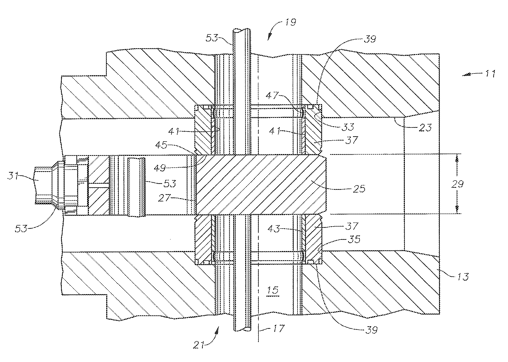
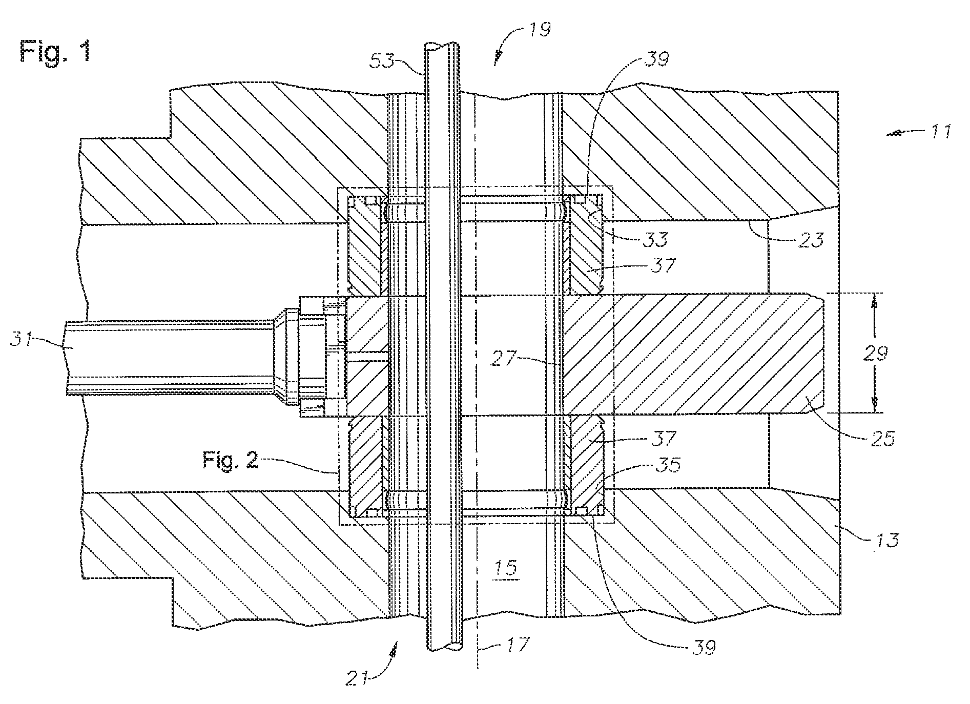
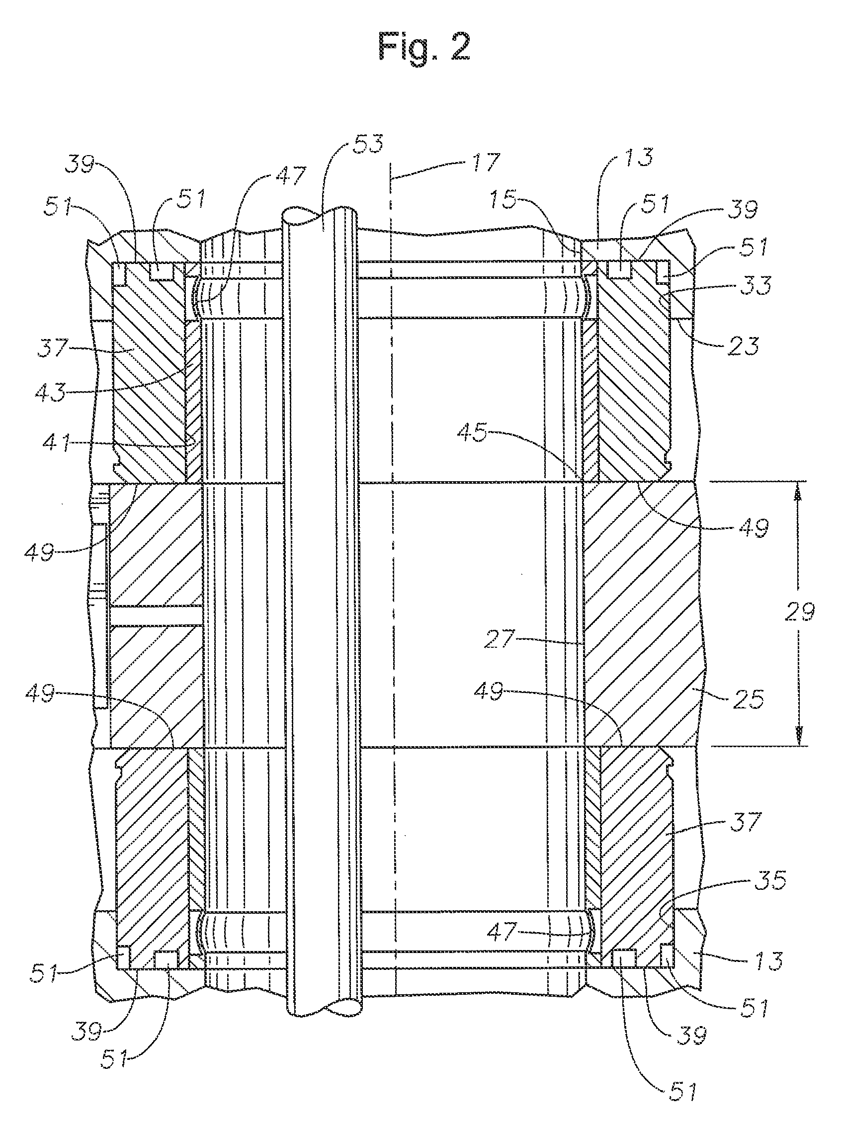
The disclosed embodiments of the patent provide a protective inner sleeve for the valve seat during shearing of members, as well as a replaceable inner sleeve that can be used without replacing the seat after repeated uses. The inner sleeve is also hard enough to act as a cutting surface for shearing wireline or coiled tubing. Additionally, the inner sleeve is compressible to ensure the valve still seals to the gate even if debris is trapped between the sleeve and the gate.

Problems solved by technology

The action of shearing any downhole tooling requires significant loads and very high localized stresses on the gates and seats involved.
This stressing can lead to damage or general degradation of the surface finish on any of the sealing faces of the gates and seats adjacent to the edges where this shearing occurs.
This surface damage to the sealing faces of the gate and the seat can cause sealing problems when the valve is closed, leading to leakage.
Currently there are issues with the sealing of gate valves after shearing of coiled tubing, wireline, or a combination of both.
As the movement of the gate presses the wireline or coiled tubing against the valve seat, the sealing faces of the valve seat adjacent the gate and interior of the valve may significantly deteriorate.
A protective barrier may be placed between the seat and the wireline or coiled tubing to limit the damage to the seat; however, these barriers may become misaligned during operation and interfere with the seats ability to seal to the gate.

Method used


Image

  • Split seat shear valve
  • Split seat shear valve
  • Split seat shear valve

Examples


Embodiment Construction

[0020]The present invention will now be described more fully hereinafter with reference to the accompanying drawings which illustrate embodiments of the invention. This invention may, however, be embodied in many different forms and should not be construed as limited to the illustrated embodiments set forth herein. Rather, these embodiments are provided so that this disclosure will be thorough and complete, and will fully convey the scope of the invention to those skilled in the art. Like numbers refer to like elements throughout, and the prime notation, if used, indicates similar elements in alternative embodiments.

[0021]In the following discussion, numerous specific details are set forth to provide a thorough understanding of the present invention. However, it will be obvious to those skilled in the art that the present invention may be practiced without such specific details. Additionally, for the most part, details concerning valve construction, operation, use, and the like have...


PUM


Abstract

A gate valve has a gate valve seat for sealing a valve body to a gate of the gate valve. The valve seat extends from a flow passage of the valve body into a cavity of the valve body parallel to an axis of the flow passage. The cavity is perpendicular to the flow passage, and the gate is disposed within the cavity. The valve seat has a tubular body having a face for contact with a gate, and an end opposite the face adjacent to and in contact with the valve body. The valve seat also includes a sleeve positioned on an inner diameter of the tubular body, the sleeve adapted to receive a shear force for shearing a member extending through the flow passage, the inner sleeve having an adjustable length.

Description

BACKGROUND OF THE INVENTION[0001]1. Field of the Invention[0002]The present invention relates in general to slab style gate valves and, in particular, to a shear gate valve having a valve seat with a deformable inner sleeve.[0003]2. Brief Description of Related Art[0004]A production bore intervention valve may be used on a subsea oil and gas work over riser system. The work over riser system provides safe access to the production bore during well intervention activities. The intervention valve provides a means to control well bore fluids and also to allow the platform to disconnect from the well during an emergency situation. Closure of the valve may be required when downhole tooling such as coiled tubing or wireline are still running through the valve. The valve must be capable of severing the coiled tubing or wireline to allow the valve to close, while maintaining the valve's function as a fluid barrier.[0005]A typical gate valve used in connection with oil and gas production has ...

Claims


Application Information

Patent Timeline
Patent Type & Authority Patents(United States)
IPC IPC(8): E21B33/06F16K3/02
CPCF16K3/0263E21B33/063
Inventor ALEXANDER, DAVID JAMESPALANISAMY, PRABHUHASHEMIZADEH, HUSSAIN
Owner VETCO GRAY U K
Learn More