Self contained irradiation system using flat panel X-ray sources

a x-ray source and self-contained technology, applied in the direction of x-ray tube target materials, x-ray tube targets, convertors, etc., can solve the problems of occupying valuable floor space, cumbersome operation, and weighing three or four tons, and achieves smoothing out the flux distribution, and reducing the cost of operation.

Active Publication Date: 2016-04-26
STELLARRAY
View PDF16 Cites 4 Cited by
  • Summary
  • Abstract
  • Description
  • Claims
  • Application Information

AI Technical Summary

Benefits of technology

[0023]Embodiments of the present disclosure provide an irradiation system and method wherein the X-ray flux generation area of a substantially planar source is substantially equal to the proximate target surface area facing X-ray flux generation area. The system utilizes a flat panel X-ray source, which generates high intensity X-ray flux over a large area. As this X-ray flux generation area is substantially planar, the X-ray flux remains substantially uniform within the irradiation chamber. One or more flat panel X-ray sources are placed around the irradiation chamber to generate X-ray flux. The design of the present disclosure provides a compact, efficient and safe irradiation system.
[0024]Embodiments of the present disclosure provide a compact, safe and highly efficient self-contained X-ray irradiation system that offers significant advantages over prior art approaches. More specifically, the present disclosure provides a compact system for X-ray irradiation wherein the X-ray flux generation area of a source is substantially equal to the proximate facing surface area of the material to be irradiated. The irradiator includes at least one flat panel X-ray source which generates a wide source of X-ray flux. One or more flat panel X-ray sources are disposed between the irradiator enclosure and the area in which the irradiation takes place, so that the X-ray flux is directed inward towards the material to be irradiated. The flux exit windows of the sources face the material to be irradiated and the anode targets sources face the irradiator enclosure. Much of the X-ray flux which passes by or through the material being irradiated will be absorbed by the anode target of an opposite flat panel X-ray source, providing a degree of self-shielding and reducing the need for other shielding materials. Since the X-ray sources are wide, and the flux generation area is substantially equal to the irradiation target area, minimal throw distance is needed compared with a point source, which allows the irradiator to be made yet more compact.
[0025]According to one embodiment of the present disclosure an apparatus and method for the X-ray irradiation of materials. This apparatus includes an irradiation chamber, a number of flat electromagnetic (X-ray) sources, a support mechanism, a heat transfer system, and a shielding system. A shielded portal within the shielding system allows access to an interior volume of the irradiation chamber. The shielded portal allows materials to be placed in and withdrawn from the irradiation chamber. When closed, the shielded portal allows a continuous shielded boundary of the interior volume of the irradiation chamber. The electromagnetic sources are positioned on or embedded with interior surfaces of the irradiation chamber. These electromagnetic sources may generate an electromagnetic flux, such as an X-ray flux, where this flux is used to irradiate the interior volume of the irradiation chamber and any materials placed therein. The materials placed within the interior of the chamber may be supported by a low attenuation support mechanism. This low attenuation support mechanism does not substantially reduce the X-ray flux intended to irradiate the materials placed within the interior volume of the irradiation chamber. Additionally the irradiation chamber may have a heat transfer system thermally coupled to the irradiation chamber and electromagnetic sources in order to remove heat from the interior surfaces of the irradiation chamber. The shielding system external to the irradiation chamber prevents unwanted radiation from escaping from within the irradiation chamber.
[0026]Another embodiment of the present disclosure provides a method for the X-ray irradiation of materials. This method involves transporting a work piece or material to be irradiated to an irradiation chamber. The work piece or materials are placed within the irradiation chamber and supported with a mechanism such as a low attenuation support mechanism. This low attenuation support mechanism does not substantially reduce the electromagnetic flux (X-ray) flux within the irradiation chamber. One or more flat electromagnetic (X-ray) sources may be energized to irradiate the interior volume of the irradiation chamber. This allows the work piece or materials to be irradiated within the chamber. Excess heat may be removed with a heat transfer system in order to prevent the irradiation chamber / electromagnetic source from overheating. Additionally the irradiation chamber may be shielded to prevent the irradiation of objects and materials external to the irradiation chamber.
[0027]Yet another embodiment of the present disclosure provides another system for the X-ray irradiation of materials. This system includes an irradiation chamber, a number of flat X-ray sources, a transport mechanism, a low attenuation support mechanism, a heat transfer system, a shielding system, and a process controller. The irradiation chamber has an inner volume wherein the flat X-ray sources are positioned within or on the interior surfaces of the irradiation chamber such that the flat X-ray sources may irradiate the interior volume of the irradiation chamber. The transport mechanism allows materials to travel to and from the irradiation chamber. Within the irradiation chamber the low attenuation support mechanism supports the work pieces or materials to be irradiated while not substantially reducing the X-ray flux available for the irradiation of these objects. The heat transfer system removes heat from the X-ray source and the shielding system external to the irradiation chamber prevents inadvertent irradiation of materials and objects outside the irradiation chamber. The process controller coordinates the operation of the irradiation chamber, X-ray source, heat transfer system and an interlock system which prevents irradiation while access to the interior volume is open.

Problems solved by technology

These higher doses necessitate heavier shielding, so these units are larger and often weigh three or four tons.
Even the smaller Cs-137 units take up valuable floor space at blood banks and hospitals and are cumbersome to operate.
Security concerns have added substantially to the acquisition and operating costs of irradiators using Cs-137.
Though X-rays have long been known as a possible substitute radiation source for many of the uses of isotope-based self-contained irradiators, including blood irradiation [Janatpour 2005], several limitations of prior art X-ray irradiators have prevented their adoption.
Those which go back into the target will not be useful for irradiation, but will instead generate heat.
Furthermore, since all the flux needed for the application must come from one spot on the anode, there is a tremendous thermal load on this small area, which in turn necessitates the use of complex liquid cooling systems for higher flux applications.
Even with more than one tube, the use of a point source of X-rays still places a tremendous heat load on one spot, so externally-connected liquid cooling systems are still needed.
In practice, these have proven to be cumbersome and unreliable, thereby limiting the adoption of X-ray systems for blood irradiation [Dodd, 2009].
Two major limitations of this kind of source are the thermal loading capacity of the thin-film anode, and the thermal matching of the anode to the exit window of the source.
Even with externally-connected liquid cooling systems, only limited amounts of X-ray power can be obtained from this kind of source.
X-rays produced by the lower, “reflective” anode will be attenuated first by the cathode arrays and their support structures, and then the thin-film X-ray target, resulting in an inefficient system.
The heat must therefore be transferred through the vacuum enclosure, which will limit the amount of X-ray flux that can be achieved with this source.

Method used


Image

  • Self contained irradiation system using flat panel X-ray sources
  • Self contained irradiation system using flat panel X-ray sources
  • Self contained irradiation system using flat panel X-ray sources

Examples


Embodiment Construction

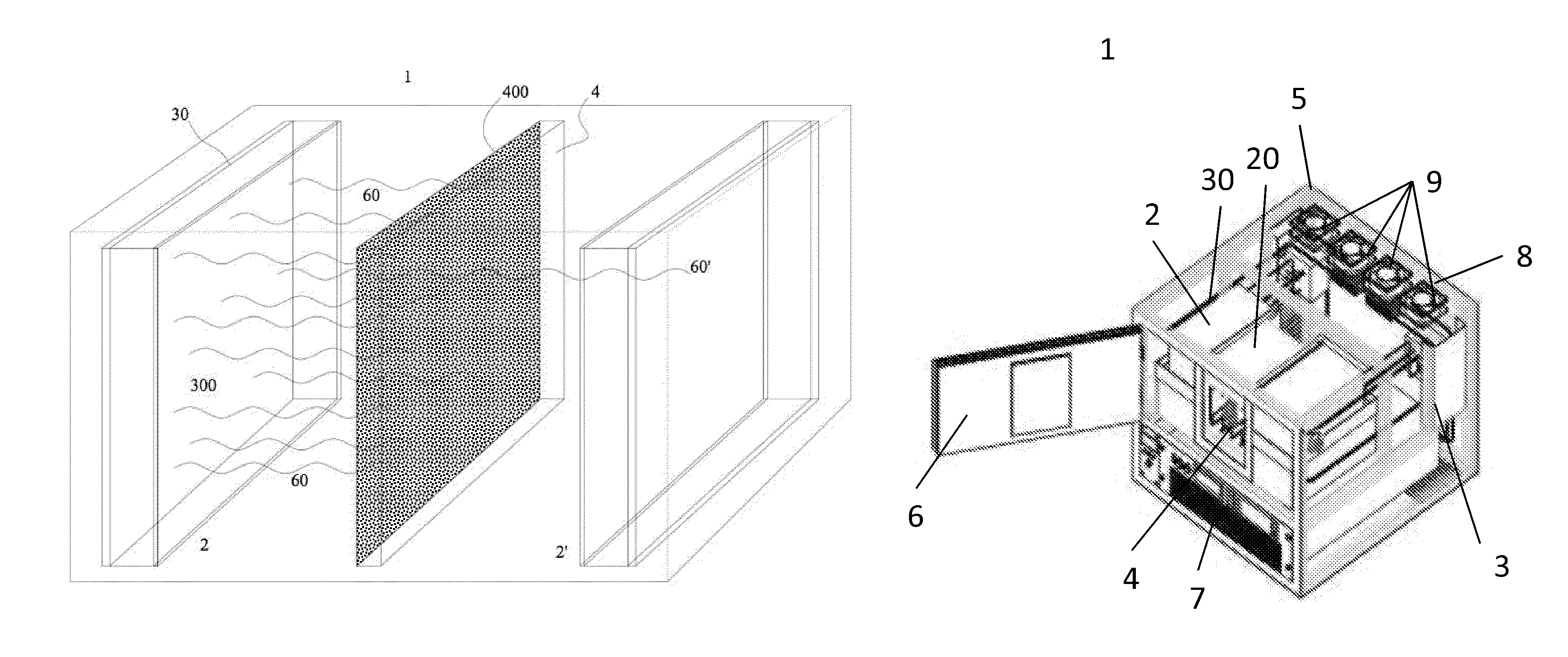
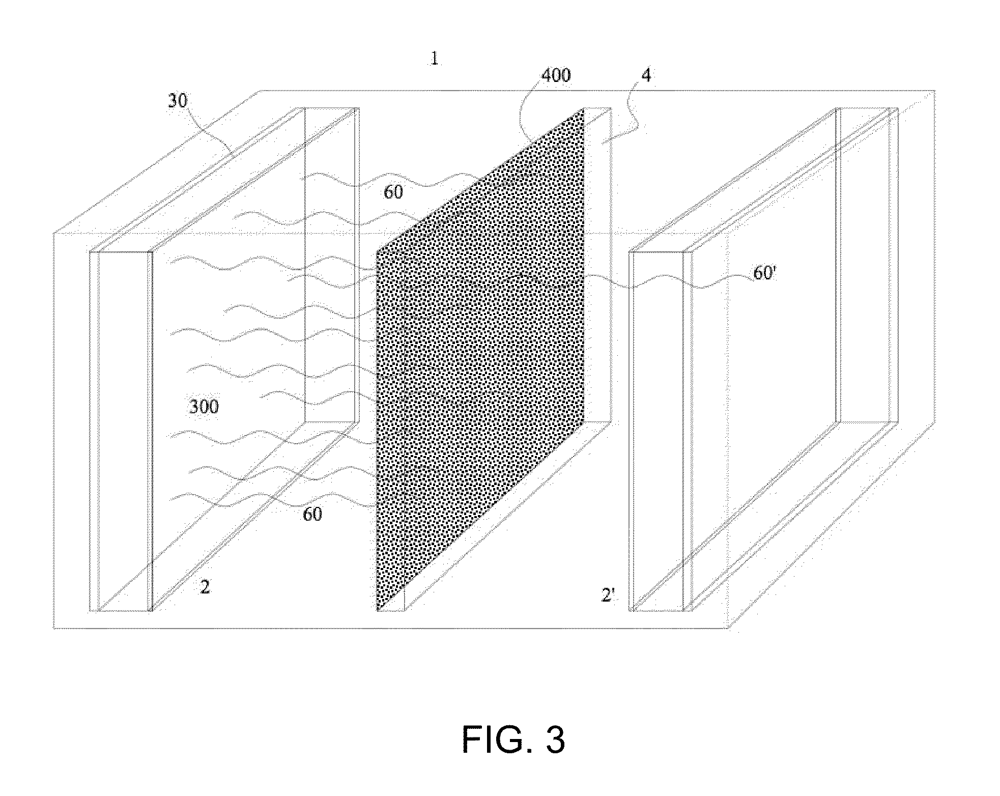
[0040]Preferred embodiments of the present disclosure are illustrated in the FIGs., like numerals being used to refer to like and corresponding parts of the various drawings.

[0041]Embodiments of the present disclosure provide an apparatus and method for the X-ray irradiation of materials. This apparatus includes an irradiation chamber, a number of flat electromagnetic (X-ray) sources, a support mechanism, a heat transfer system, and a shielding system. A shielded portal within the shielding system allows access to an interior volume of the irradiation chamber. The shielded portal allows materials to be placed in and withdrawn from the irradiation chamber. When closed, the shielded portal allows a continuous shielded boundary of the interior volume of the irradiation chamber. The electromagnetic sources are positioned on or embedded with interior surfaces of the irradiation chamber. These electromagnetic sources may generate an electromagnetic flux, such as an X-ray flux, where this ...


PUM

PropertyMeasurementUnit
thicknessaaaaaaaaaa
atomic numberaaaaaaaaaa
thicknessaaaaaaaaaa

Abstract

The present disclosure describes a self-contained irradiator comprising at least one X-ray source inside a shielded enclosure, the one or more sources each operable to emit X-ray flux across an area substantially equal to the proximate facing surface area of material placed inside the enclosure to be irradiated. The irradiator may have multiple flat panel X-ray sources disposed, designed or operated so as to provide uniform flux to the material being irradiated. The advantages of the irradiator of the present disclosure include compactness, uniform flux doses, simplified thermal management, efficient shielding and safety, the ability to operate at high power levels for sustained periods and high throughput.

Description

REFERENCES TO RELATED APPLICATIONS[0001]The present U.S. Utility patent application claims priority pursuant to 35 U.S.C. §120, as a continuation-in-part (CIP), to the following U.S. Utility patent application which is hereby incorporated herein by reference in its entirety and made part of the present U.S. Utility Patent Application for all purposes:[0002]1. U.S. Utility application Ser. No. 12 / 201,741, entitled “FLAT PANEL X-RAY SOURCE,” filed Aug. 29, 2008, issued as U.S. Pat. No. 8,155,273 on Apr. 10, 2012, which claims priority pursuant to 35 U.S.C. §120 as a continuation to the following U.S. patent application which is hereby incorporated herein by reference in its entirety and made part of the present U.S. Utility Patent Application for all purposes:[0003]a. U.S. Utility application Ser. No. 11 / 355,692, entitled “COMPACT RADIATION SOURCE,” filed Feb. 16, 2006.[0004]The present U.S. Utility patent application also claims priority pursuant to 35 U.S.C. §119(e) to the following...

Claims


Application Information

Patent Timeline
Patent Type & Authority Patents(United States)
IPC IPC(8): G21K5/00H01J35/06H01J35/18H01J35/16H01J35/14A61L2/08G21K1/02G21K5/02H01J35/08
CPCA61L2/082G21K1/025G21K5/02H01J35/06H01J35/065H01J35/08H01J35/14H01J35/16H01J35/18A61L2202/14A61L2202/22A61L2202/23A61L2202/24H01J2235/068H01J2235/081H01J2235/086H01J2235/087H01J2235/163H01J2235/18H01J35/112H01J35/116
Inventor EATON, MARKMORE, MITALIOLLA, MIKE
Owner STELLARRAY
Why Eureka
Try Eureka