
Non-contact tonometer, control method of the same, and program

a tonometer and non-contact technology, applied in the field of tonometers, can solve the problems of difficult control of the rotary solenoid alone, excessive burden on patients, and continued movement of the piston for a while, so as to reduce the movement of the piston, and reduce the burden on patients.

Active Publication Date: 2016-05-03
CANON KK
View PDF5 Cites 2 Cited by
  • Summary
  • Abstract
  • Description
  • Claims
  • Application Information

AI Technical Summary

Benefits of technology

[0007]The present invention to solve the above-mentioned temporal problem and decrease a movement of a piston by inertia. Furthermore, the present invention is to provide a non-contact tonometer that reduces air to be blown and further decreases burdens on a patient, a control method of the same, and a program.
[0009]The piston is not controlled on the basis of a corneal shape deformation signal, but a movement of the piston is beforehand restricted to a predetermined displacement amount, so that air unnecessarily blown to an eye to be inspected can be reduced.

Problems solved by technology

However, even after the energization to the rotary solenoid is turned off, the piston continues to move for a while by an inertia force.
Therefore, the air unnecessary for the tonometry is blown to an eye to be inspected, and hence an excessive burden is imposed on a patient.
Therefore, it is difficult for the rotary solenoid alone to execute control so that the piston advancing in the pressurizing direction of the air is rapidly decelerated, stopped or moved backward.
Therefore, in the above-mentioned prior arts, the time required for the control is excessively long, and hence temporally difficult to reduce the air to be blown.

Method used


Image

  • Non-contact tonometer, control method of the same, and program
  • Non-contact tonometer, control method of the same, and program
  • Non-contact tonometer, control method of the same, and program

Examples


first embodiment

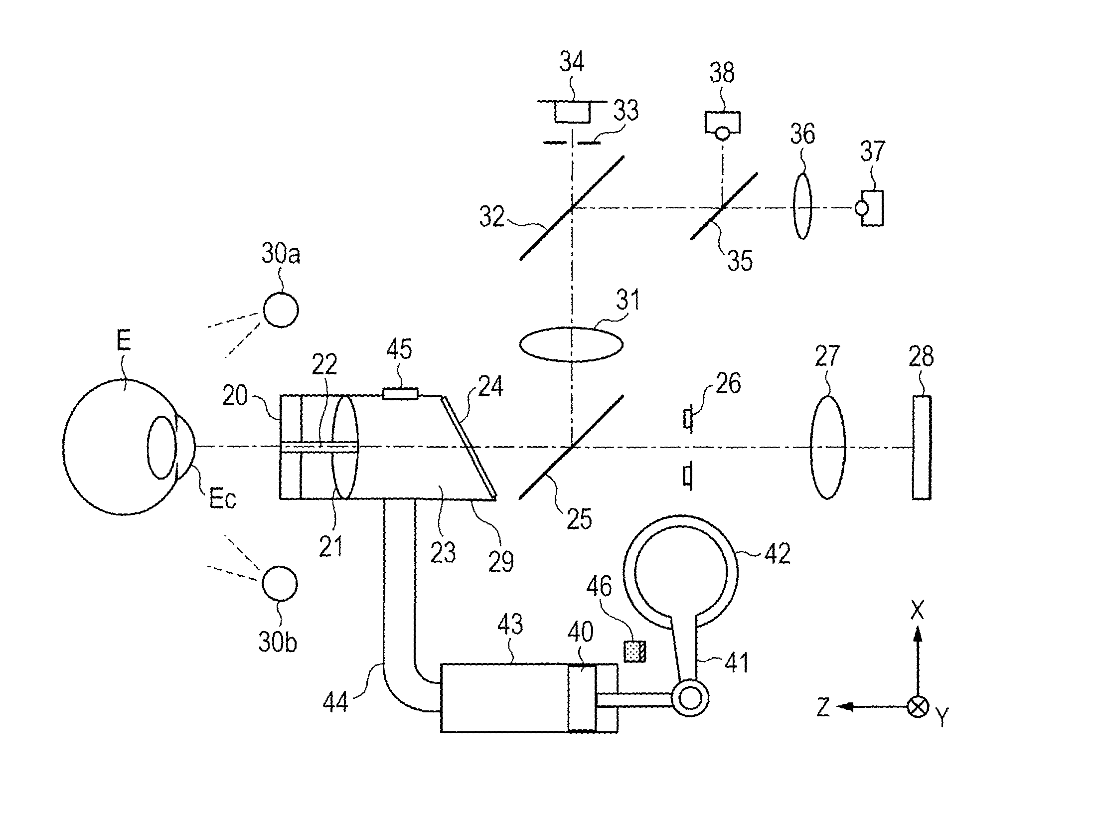
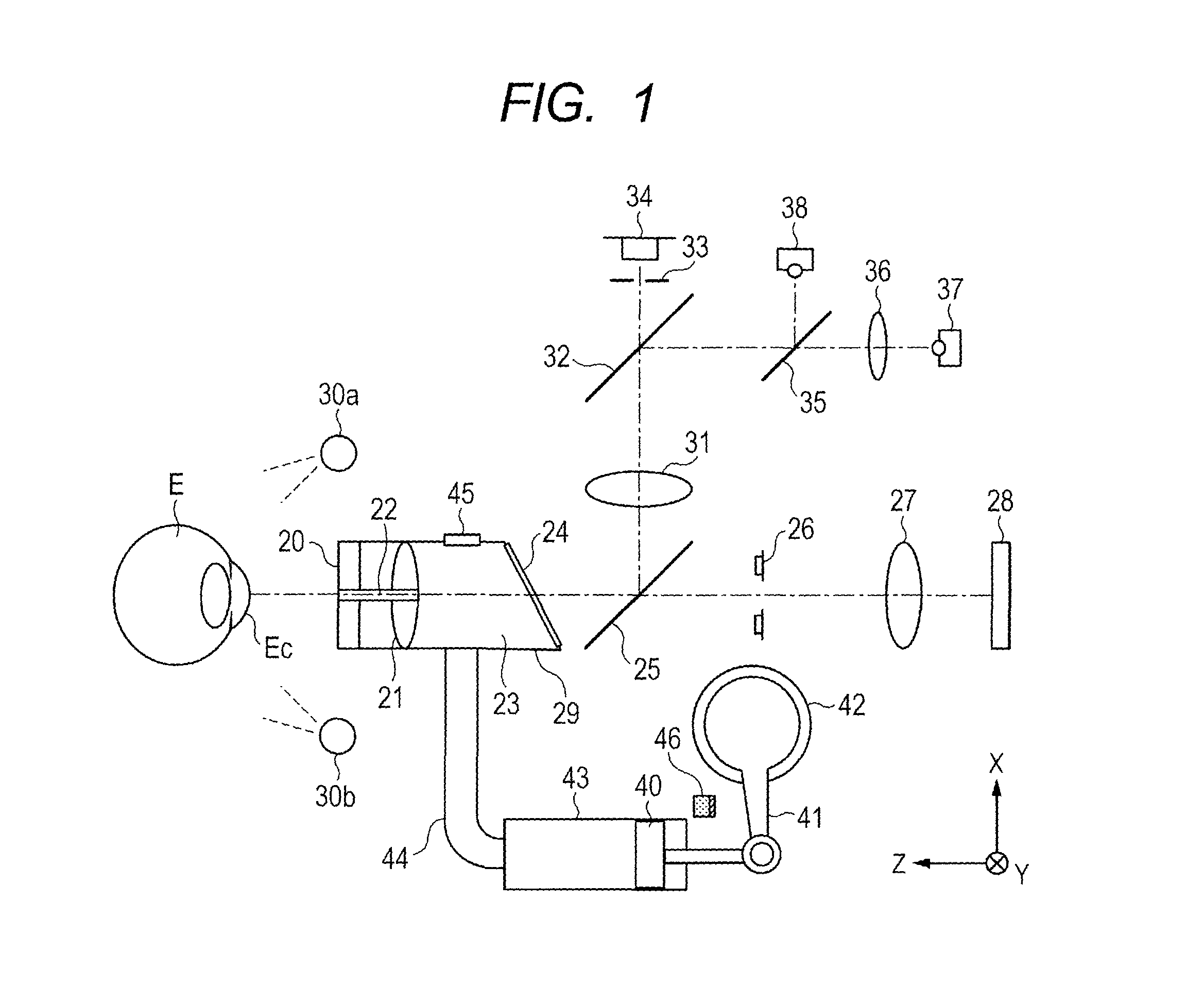
[0021]A schematic constitutional view of a non-contact tonometer of a first embodiment of the present invention is shown in FIG. 1.

[0022]First, description of an optical system of the present apparatus is made. A measuring light source 37 is a near infrared LED to be used for measurement and also for alignment to an eye E to be inspected. In an emitting direction of the measuring light source 37, a projection lens 36, a half mirror 35 and a half mirror 32 are arranged. In a reflecting direction of the half mirror 35 as seen from the half mirror 32, there is disposed a fixation light source 38 as an LED to be seen by a patient in a fixed manner. In a reflecting direction of the half mirror 32 as seen from the half mirror 35, a relay lens 31 is disposed.

[0023]A nozzle 22 is disposed to face a cornea Ec of the eye E to be inspected on a central axis of a parallel flat glass 20 and an objective lens 21. Behind the nozzle, an air chamber 23, an observation window 24, a dichroic mirror 25...


PUM


Abstract

An excessive amount of pressurized air is inhibited from being blown to an eye of a patient during measurement of a corneal shape deformation amount. In a non-contact tonometer having a piston, a driving unit to drive the piston, a fluid ejection unit to blow air pressurized by driving the piston toward a cornea of an eye to be inspected, and an intraocular pressure measuring unit to detect a deformed state of the cornea and measure an intraocular pressure, there are provided a piston displacement restricting unit that restricts a displacement amount when the piston pressurizes the air, and a changing unit to change the displacement amount to be restricted by the piston displacement restricting unit.

Description

BACKGROUND OF THE INVENTION[0001]1. Field of the Invention[0002]The present invention relates to a non-contact tonometer that calculates an intraocular pressure value from a corneal shape deformation detection signal when air is blown to an eye to be inspected, a control method of the same, and a program to execute the control method.[0003]2. Description of the Related Art[0004]Many of non-contact tonometers have constitution where a piston pushes air in a cylinder outwardly, to pressurize the air in an air chamber, and the pressurized air is ejected from a nozzle. For the driving of the piston, a rotary solenoid is usually used because an initial torque of the rotary solenoid is strong and a stroke thereof is long. Furthermore, control is executed to turn off energize to the rotary solenoid on the basis of a corneal shape deformation detection signal, when a cornea is deformed into a predetermined state that is necessary for tonometry. However, even after the energization to the ro...

Claims


Application Information

Patent Timeline
Patent Type & Authority Patents(United States)
IPC IPC(8): A61B5/00A61B3/16
CPCA61B3/165
Inventor SHIMOZATO, YUKI
Owner CANON KK
Learn More