
Pump arrangement

a technology of pump and arrangement, applied in the field of mechanical engineering and fine mechanics, can solve the problems of high manufacturing effort required in the manufacture of the pump to reduce the blood-damaging effect of the moving pump parts, the blood-damaging effect, and the geometries of the pump which cannot be used by means of minimally invasive procedures, and achieve the effect of lightening the introduction of the pump

Active Publication Date: 2016-05-03
ECP ENTWICKLUNGSGMBH
View PDF249 Cites 82 Cited by
  • Summary
  • Abstract
  • Description
  • Claims
  • Application Information

AI Technical Summary

Benefits of technology

The present invention aims to minimize the risk of damage to blood or fluid during pumping. This is done by carefully selecting materials that meet the requirements of biocompatibility and do not cause interactions with foreign surfaces that could lead to blood damage. The third factor, interactions with foreign surfaces, has been well-examined and is also being addressed in the invention to ensure safer pumping.

Problems solved by technology

Since all blood comes into direct contact with the pump, a particularly high effort is required in the manufacture of the pump to reduce the blood-damaging effect of the moving pump parts.
This blood-damaging effect is manifested in direct mechanical shear at moving and stationary pump parts and in shear by shear stress fields occurring in the fluid while passing through the flow passage (see above).
Pump geometries therefore also arise which cannot be used by means of a minimally invasive procedure.

Method used


Image

  • Pump arrangement
  • Pump arrangement
  • Pump arrangement

Examples


Embodiment Construction

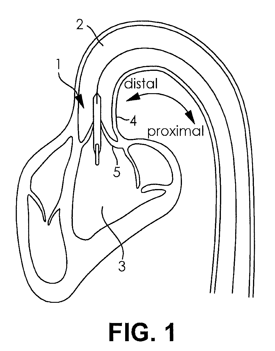
[0043]A possible use for the pump arrangement 1 is shown in FIG. 1. The pump arrangement 1 includes an elongate catheter which extends through the blood vessel 2 and in which a shaft extends which drives the pump present in the pump arrangement 1 and formed as a rotor. The proximal end of the pump arrangement (viewed without the catheter) is located in the blood vessel 2, whereas the distal end of the pump arrangement 1 including the pump is located in the ventricle 3. The blood vessel 2 is bounded by the vessel wall 4. The valve 5 which opens and closes rhythmically furthermore bounds the ventricle 3 and enables the blood flow from the ventricle 3 into the blood vessel 2.

[0044]Further uses are possible in addition to the shown use of a pump arrangement in accordance with the information. The pump can thus, for example, be used in a different vessel of the body to increase the conveying performance.

[0045]The mode of operation of a pump arrangement in accordance with the invention sh...


PUM


Abstract

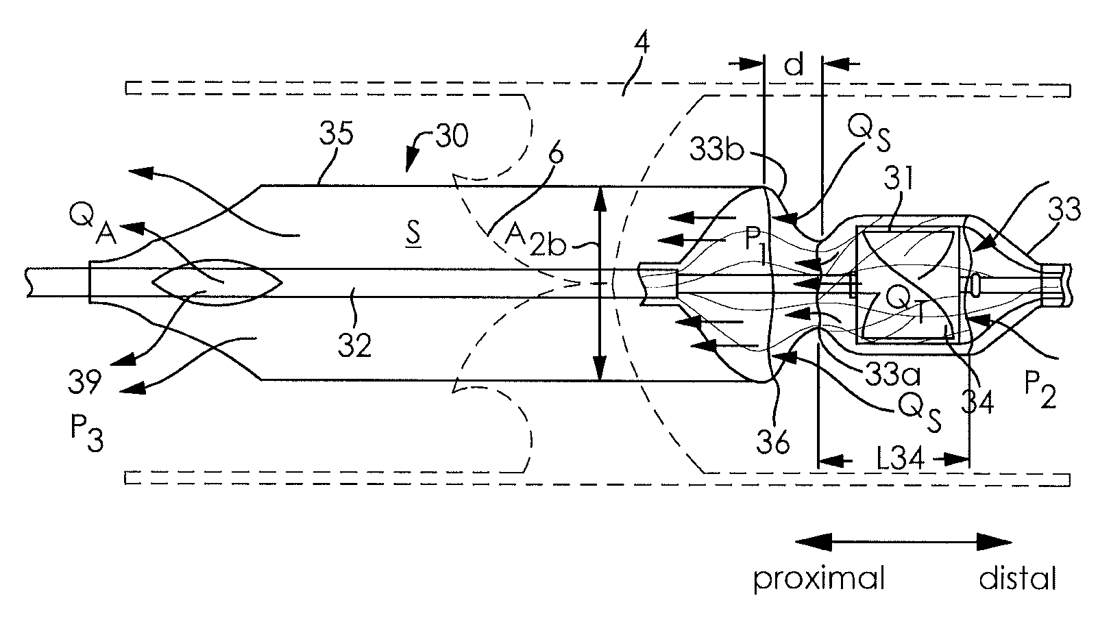
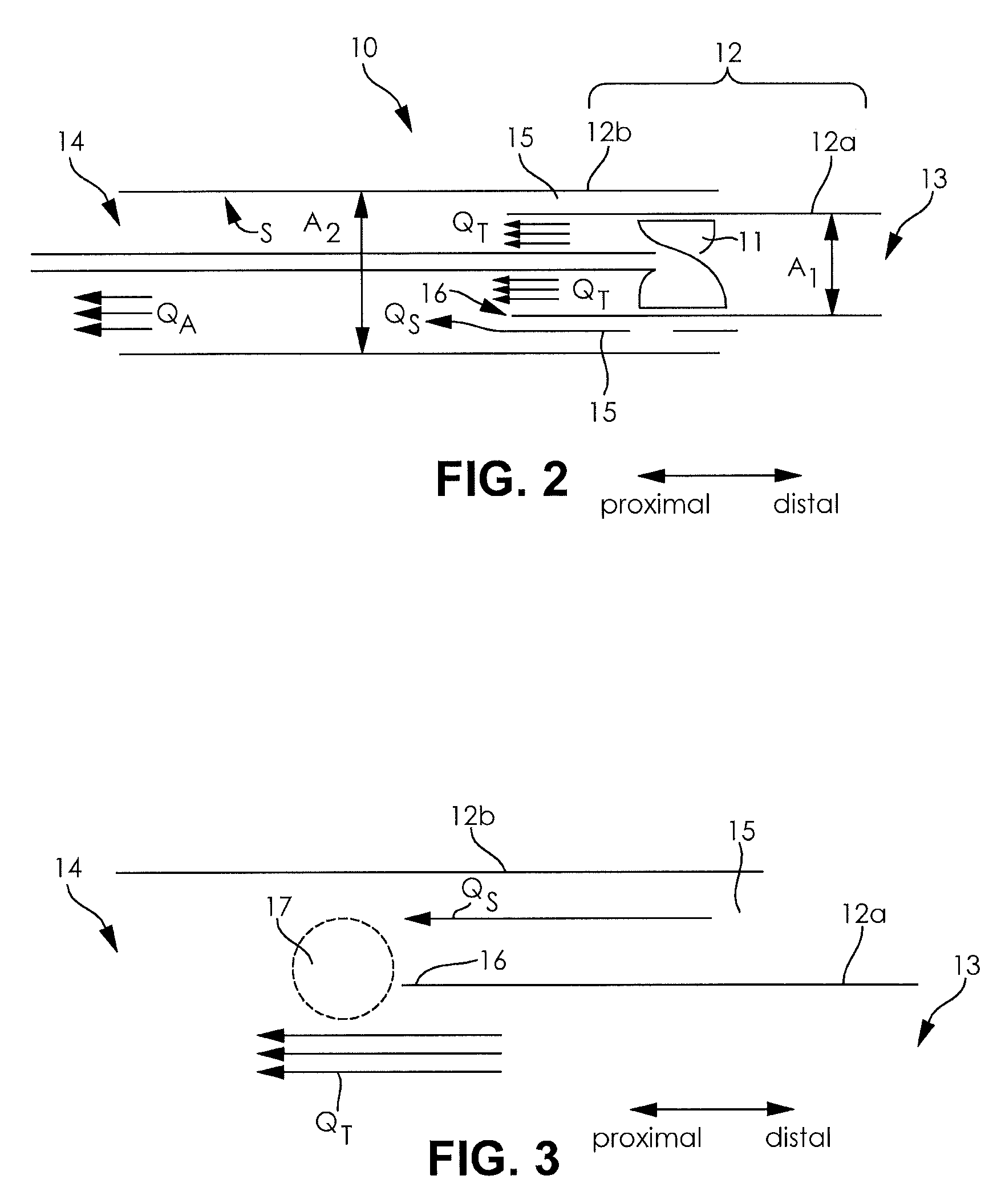
The subject matter of the present invention is a pump arrangement, in particular for use in the body's own vessels, having a pump and a sheath receiving the pump, bounding a flow passage and having a distal intake opening and a proximal outflow opening for producing a driving flow by means of the pump, wherein the pump is arranged in a first fluid-tight section having the distal intake opening and a second fluid-tight section includes the proximal outflow opening. In accordance with the invention, a further inlet opening is present between the first section, and the second section and is arranged between the intake opening and the outflow opening, with the first section and the second section being arranged with respect to one another such that the inlet opening opens into the flow proximal to the pump.

Description

BACKGROUND OF THE INVENTION[0001]The invention is in the field of mechanical engineering and fine mechanics and can in particular advantageously be used in the medical area.[0002]In this respect, the subject matter is a pump arrangement in accordance with the preamble of claim 1.[0003]Pump arrangements are increasingly known from prior art in particular for use in the body's own vessels. Said pumps can be used, for example, for short-term cardiac support to relieve the cardiac muscle of a patient after a cardiogenic shock (myocardial infaction). In this process, use is sometimes made of transfemorally implanted micro-axial pumps.[0004]Such a pump arrangement is known, for example, from EP 2 047 872 A1. The pump arrangement disclosed there includes a pump, a sheath receiving the pump and having a distal intake opening and a proximal outflow opening, with the pump generating a driving flow in operation from the distal intake opening toward the proximal outflow opening. A flow passage ...

Claims


Application Information

Patent Timeline
IPC IPC(8): A61M1/12F04F5/10A61M1/10A61M60/135A61M60/17A61M60/237A61M60/416A61M60/825
CPCF04F5/10A61M1/101A61M1/1024A61M1/1034A61M1/1084A61M1/125A61M2205/02A61M2205/04A61M60/405A61M60/135A61M60/148A61M60/17A61M60/825A61M60/237A61M60/416A61M60/414A61M60/577A61M60/211F04D3/00F04D7/00F04D29/026F04D29/181F04D29/528
Inventor LIEBING, REINER
Owner ECP ENTWICKLUNGSGMBH
Learn More