
External-control type fan clutch device

a technology of clutch device and external control, which is applied in the direction of fluid coupling, coupling, machine/engine, etc., can solve the problem of not being able to obtain the effect of reducing the unnecessary rotation of the fan at the starting time of the engine, and achieve the effect of reducing oil leakag

Active Publication Date: 2016-05-03
USUI KOKUSAI SANGYO KAISHA LTD
View PDF12 Cites 7 Cited by
  • Summary
  • Abstract
  • Description
  • Claims
  • Application Information

AI Technical Summary

Benefits of technology

[0006]The present invention has been made in order to solve the drawback of the conventional external-control type fan clutch device, and an object of the invention is to provide an external-control type fan clutch device that can suppress unnecessary rotation of a cooling fan at the time of activating a drive shaft more effectively, regardless of stop positions of an oil supply port and an oil recovery port at a stop time of the cooling fan.
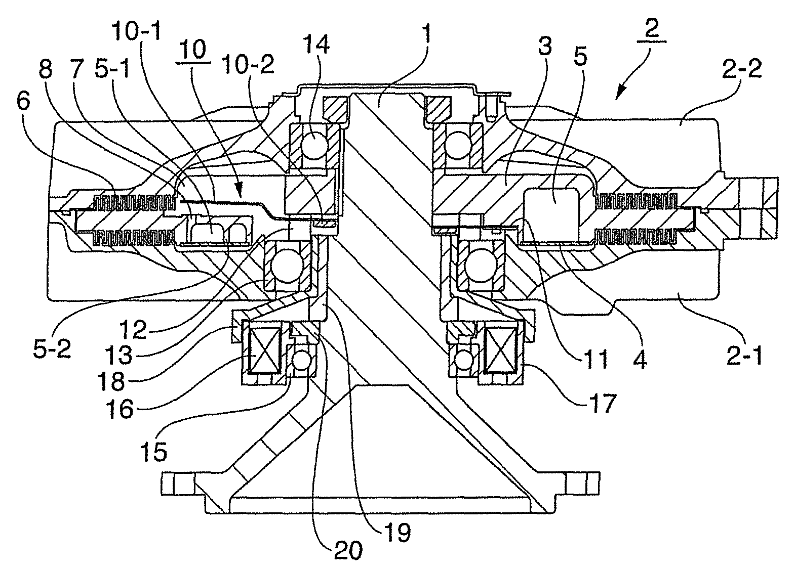
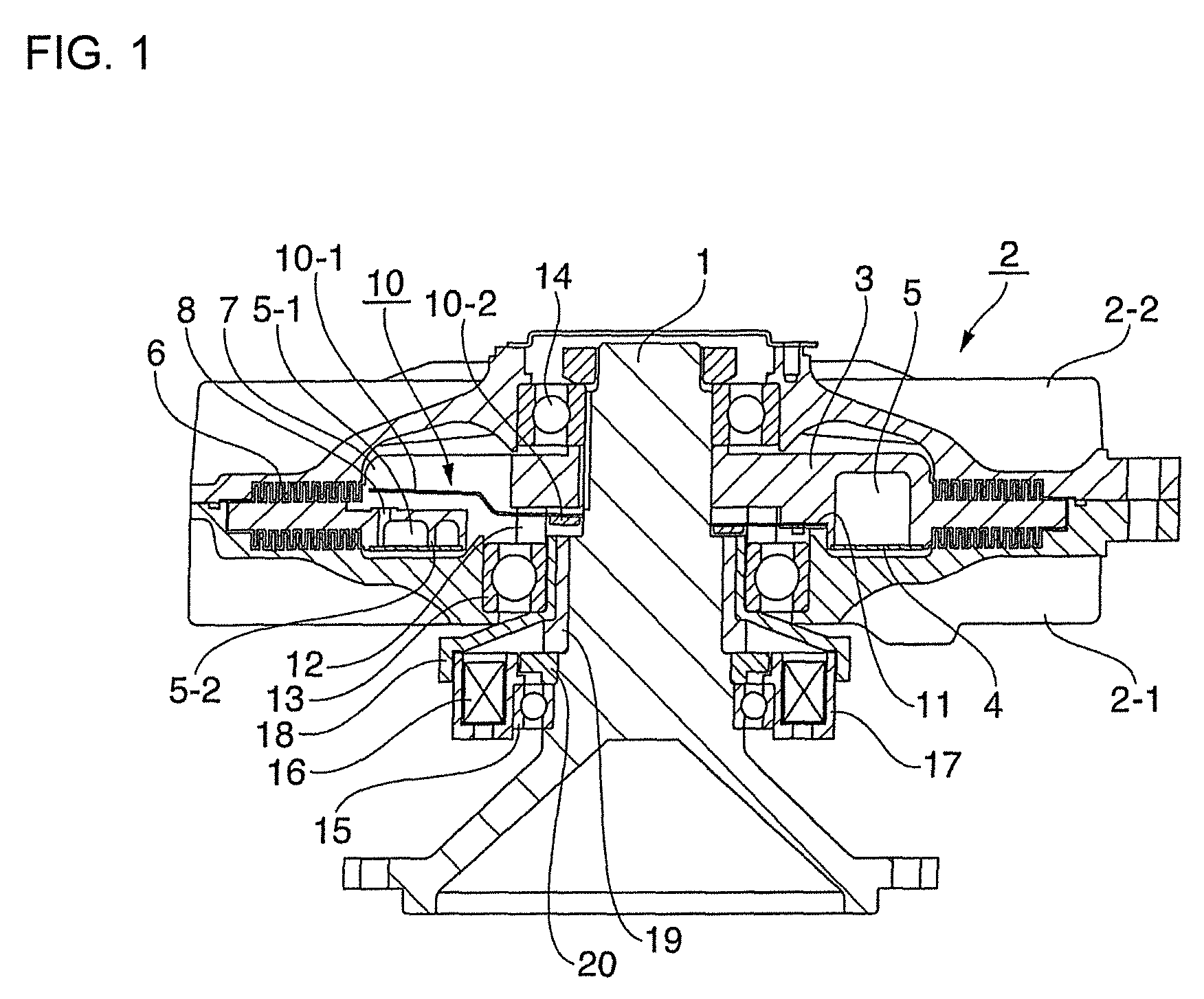
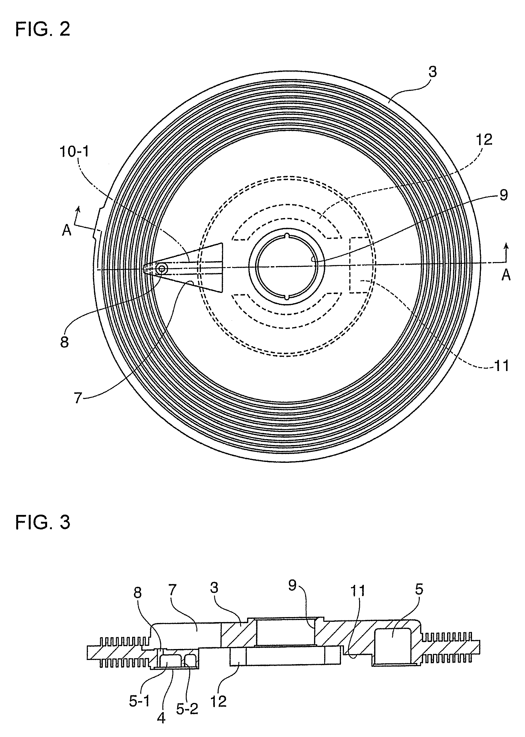
[0008]The external-control type fan clutch device according to the present invention not only can decrease oil leakage from the oil circulating flow passage hole (oil supply port) and the oil recovery port on the side of the oil reserving chamber to the side of the working chamber (torque transmission chamber) at a stop time of the cooling fan, but also can reduce an amount of leaking oil to the working chamber or can reduce the same to zero substantially regardless of stopped positions of the oil supply port and the oil recovery port by providing the oil supply chamber formed of the arc-like partition wall and the plate-like partition wall in the annular oil reserving chamber (oil storage chamber) and arranging the oil circulating flow passage hole (oil supply port) and the oil recovery port in the oil supply chamber, so that such an effect can be obtained that an unnecessary rotation of the cooling fan at the time when a drive shaft activates can be suppressed more effectively.

Problems solved by technology

However, in the case of the above-described conventional external-control type fan clutch device, since oil can be stored in the oil storage chamber at the stop time of the cooling fan, a leaking amount of oil to the working chamber can be reduced, but an amount of oil which cannot be stored in the oil storage chamber at the stop time leaks from the oil recovery port and the oil supply port due to stopping positions of the oil supply port and the oil recovery port at the stop time of the cooling fan and thereby there has been such a drawback that a suppressing effect of the unnecessary rotation of the fan at a starting time of the engine cannot be obtained sufficiently.

Method used


Image

  • External-control type fan clutch device
  • External-control type fan clutch device
  • External-control type fan clutch device

Examples


Embodiment Construction

[0014]In an external-control type fan clutch device shown in FIG. 1 to FIG. 4, a sealing housing 2 composed of a case 2-1 and a cover 2-2 is supported via bearings 13 and 14 on a rotary shaft (drive shaft) 1 rotated according to driving of a drive unit (engine), and a drive disk 3 fixed to the rotary shaft 1 is incorporated in a torque transmission chamber 6 within the sealed housing 2. As shown in FIG. 2 to FIG. 4, the drive disk 3 is configured such that an substantially triangular window hole 7 communicating with the torque transmission chamber 6 is provided at one end of an annular oil reserving chamber (oil storage chamber) 5 provided by making inside of the drive disk 3 hollow, and in addition, a mounting portion 11 for a valve member 10 described later is provided on the reverse side of the disk on the opposite side to the approximately triangular window hole 7, and arc-like disk supporting legs 12 are provided in a projecting fashion at positions opposed to each other outsid...


PUM


Abstract

Provided is an external-control type fan clutch device that can suppress unnecessary rotation of a cooling fan at the time of activating a rotary shaft effectively regardless of stop positions of an oil supply port and an oil recover port at a stop time of the fan. The fan clutch device includes a valve member for opening / closing an oil circulating flow passage hole provided on a side wall face of the annular oil reserving chamber, wherein opening / closing of the oil circulating flow passage hole is controlled by the valve member, wherein an oil supply chamber, that is formed of a partition wall composed of an arc-like wall and a plate-like partition wall for shielding one end of the arc-like partition wall, is provided in the annular oil reserving chamber, and the oil circulating flow passage hole and an oil recovery port are arranged in the oil supply chamber.

Description

BACKGROUND[0001]1. Field of the Invention[0002]The present invention generally relates to an external-control type fan clutch device that controls fan rotation for cooling engine in an automobile or the like according to a change in ambient temperature or a rotation change of an engine, and in particular, relates to an external-control type fan clutch device that can suppress unnecessary rotation of a cooling fan occurring when the cooling fan transitions from a stop state to a rotating state.[0003]2. Description of the Related Art[0004]Conventionally, as a fan clutch device of such a type, there has been known a viscous friction clutch for driving a cooling fan in a motor vehicle (see U.S. Pat. No. 7,886,886). The viscous friction clutch comprises a driving disk and a housing, an annular supply chamber and a working chamber, a supply device for supplying shear fluid (oil) from the supply chamber into the working chamber and a return device for returning the shear fluid from the wor...

Claims


Application Information

Patent Timeline
Patent Type & Authority Patents(United States)
IPC IPC(8): F16D31/00F01P7/04F16D35/02F16D48/06
CPCF16D35/024F01P7/042F16D48/064F16D2500/1022F16D2500/1027F16D2500/10418F16D2121/20
Inventor KUBOTA, SATOSHISUGAWARA, HIROKI
Owner USUI KOKUSAI SANGYO KAISHA LTD
Learn More