Method and device for active wedge error compensation between two objects that can be positioned substantially to parallel to each other

a wedge error compensation and wedge technology, applied in auxillary shaping apparatus, instruments, nanotechnology, etc., can solve the problems of small control displacement, small brake force, and no longer uniform imprinting of structures on the substra

Active Publication Date: 2016-05-03
SUSS MICRO TEC LITHOGRAPHY
View PDF20 Cites 3 Cited by
  • Summary
  • Abstract
  • Description
  • Claims
  • Application Information

AI Technical Summary

Benefits of technology

[0014]The linear actuators preferably comprise piezo elements. The deflection of the linear actuators or the deflection of the wedges takes place individually for each linear actuator or for each wedge, respectively, by means of a controller. The wedges are deflected, i.e. displaced preferably pneumatically.
[0015]In accordance with an embodiment, the linear actuators are highly precise and have in particular only small ranges of operation (control displacements also in the nm range).

Problems solved by technology

If the angle between the plane of the mask and the plane of the substrate changes, the structures are no longer uniformly imprinted in the substrate.
A problem related with passive wedge error compensation is that the brakes can hold a relatively small force of about 100 N only.
A problem related with this active wedge error compensation is the small control displacement, in particular if, e.g., piezo elements are used for the linear actuators.
In a compact system, the available constructional space is limited.

Method used


Image

  • Method and device for active wedge error compensation between two objects that can be positioned substantially to parallel to each other
  • Method and device for active wedge error compensation between two objects that can be positioned substantially to parallel to each other
  • Method and device for active wedge error compensation between two objects that can be positioned substantially to parallel to each other

Examples


Embodiment Construction

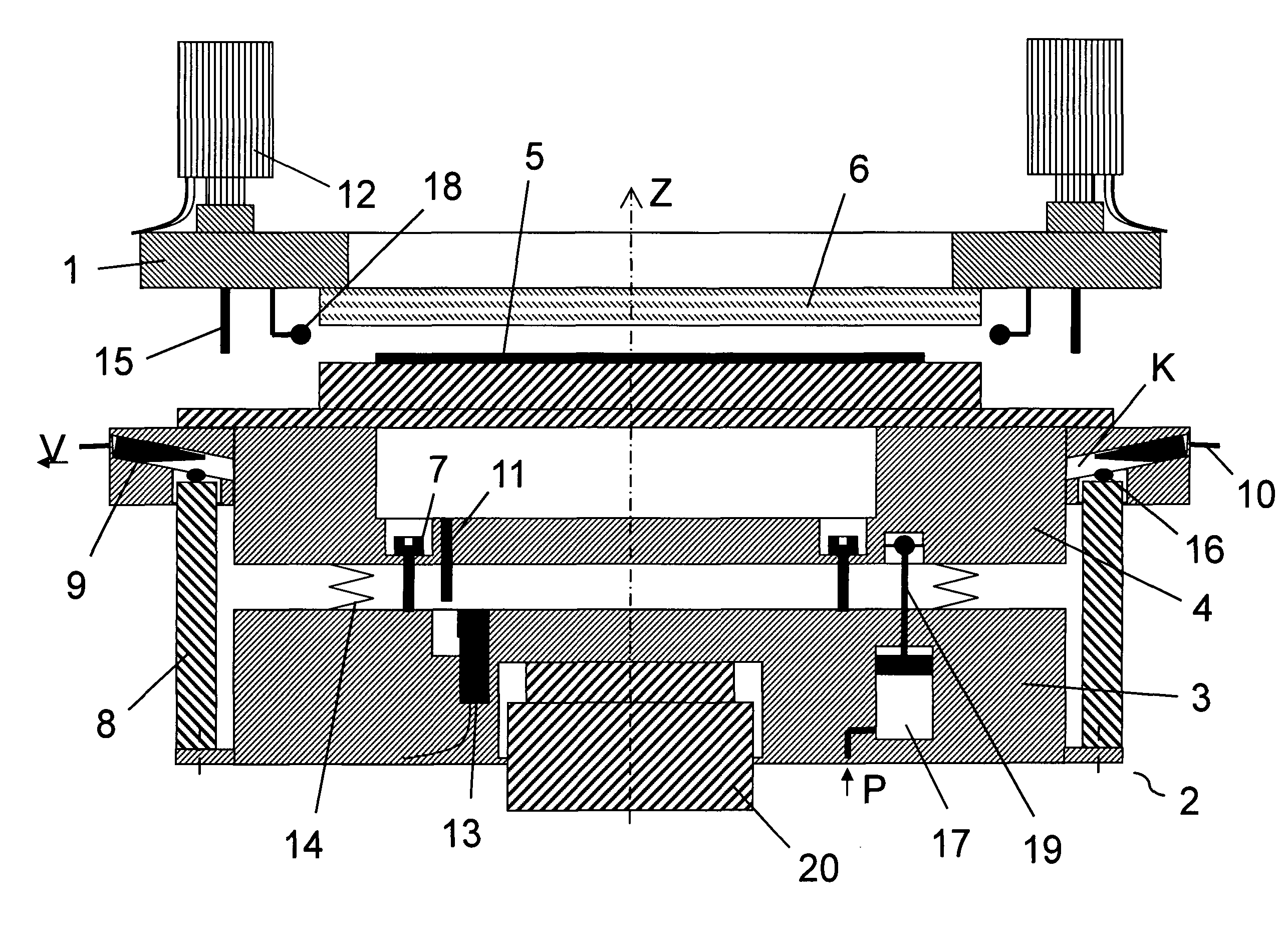
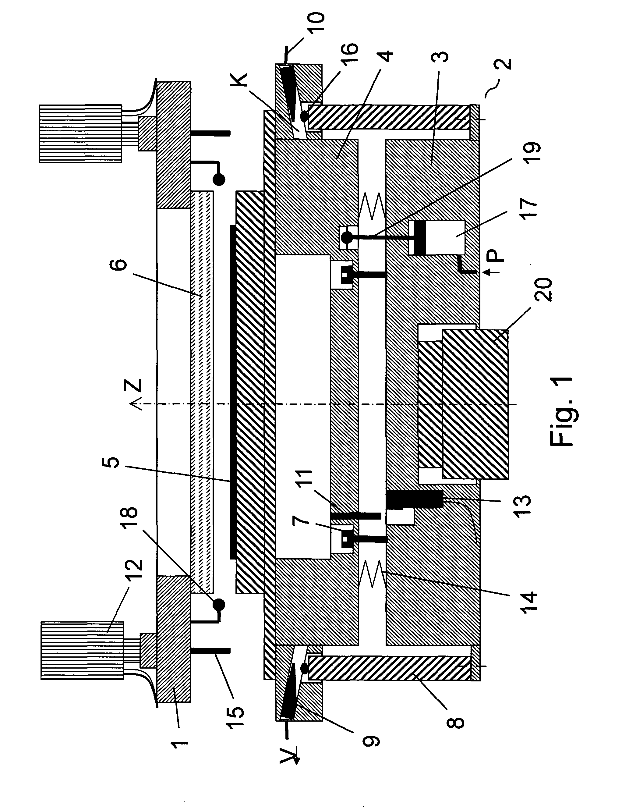
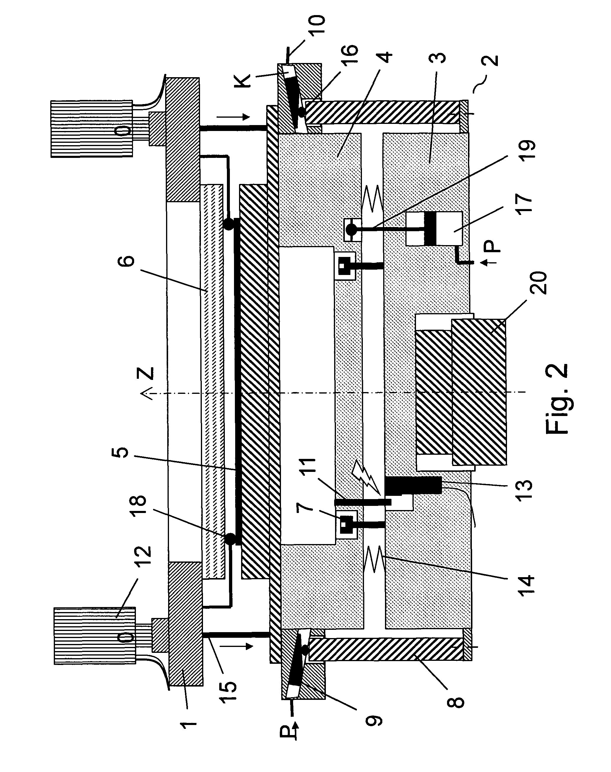
[0025]FIG. 1 shows a sectional view of a device for active wedge error compensation. The device is suitable for imprinting structures into a substrate 5. The device comprises the wedge error compensating head 2 according to the invention and a holder 1 to which a mask (or punch) 6 is fixed for imprinting the structures into the substrate 5.

[0026]The wedge error compensating head 2 comprises a movable part 4 and a stationary part 3. Pressure springs 14 are provided between the movable part 4 and the stationary part 3. By using a hydraulically or pneumatically operating means 17, the movable part 4 and the non-movable part 3 can be moved towards each other in that a piston 19, which is fixed to the movable part 4, is moved towards the stationary part 3 by a negative pressure in the means 17 located in the stationary part 3. By means of the brakes 7, the movable part 4 can be locked relative to the stationary part 3. The substrate 5 to be treated is applied to the free surface of the w...


PUM

PropertyMeasurementUnit
forceaaaaaaaaaa
displacementsaaaaaaaaaa
relative displacementaaaaaaaaaa

Abstract

The invention relates to a method and device for expanding the travel or control displacement of linear actuators that is available during an imprinting or embossing stroke. The wedge error compensating head (2) comprises a movable part (4), a stationary part (3) and at least three linear actuators (8). Each linear actuator (8) is connected to one of the parts (3, 4) at one end and to the other of the two parts (4, 3) by wedges (9) at the other end. By means of the wedges (9), it is possible to coarsely or roughly compensate for wedge errors and possible tolerances of individual subcomponents of the system. The linear actuators (8) are only used for fine or precision compensation for the wedge error. In this way, sufficient control displacement is available for the imprinting stroke with the linear actuators.

Description

[0001]This patent Application is a U.S. National Phase Patent Application from PCT Application No. PCT / EP2011 / 052141, filed Feb. 14, 2011 and claiming priority from German Patent Application No. 102010007970.7, filed Feb. 15, 2010.FIELD OF THE INVENTION[0002]The invention relates to a method and a device for wedge error compensation, and in particular to a method and a device in which the control displacement available for the wedge error compensation can be increased.BACKGROUND TO THE INVENTION[0003]When producing micro-electronic, micro-optical and micro-mechanical components, structures are transferred to a substrate by means of a mask or a punch by using embossing or imprint lithography. If the angle between the plane of the mask and the plane of the substrate changes, the structures are no longer uniformly imprinted in the substrate. This situation is referred to as wedge error. Therefore, wedge error compensation substantially determines the quality of the imprint.[0004]In pri...

Claims


Application Information

Patent Timeline
Patent Type & Authority Patents(United States)
IPC IPC(8): B29C43/58B82Y40/00G03F7/00B82Y10/00B29C43/02
CPCG03F7/0002B29C43/58B82Y10/00B82Y40/00B29C2043/025B29C2043/5858
Inventor HANSEN, SVENCONRADI, MATTHIASFINK, GEORG
Owner SUSS MICRO TEC LITHOGRAPHY
Why Eureka
Try Eureka