Air cleaner in two-stroke engine

a two-stroke engine and air cleaner technology, applied in the direction of air cleaners for fuel, charge feed systems, fuel addition of non-fuel substances, etc., can solve the problems of high air tightness required when the choke valve closes the openings, the operation system of the choke valve is complex, and the entire device associated with the stratified scavenging two-stroke engine is increased in size, so as to achieve the effect of high air tightness, small angle range, and small work rang

Active Publication Date: 2014-11-04
MITSUBISHI HEAVY IND MEIKI ENGINES CO LTD
View PDF15 Cites 3 Cited by
  • Summary
  • Abstract
  • Description
  • Claims
  • Application Information

AI Technical Summary

Benefits of technology

[0013]Accordingly, in view of such a problem in the conventional technique, an object of the present invention is to provide an air cleaner in two-stroke engines, which employs a pivotable choke valve so as to readily achieve high airtightness when closing inlets, the choke valve being capable on its own of simultaneously opening and closing both inlets of an air passage and an air / fuel mixture passage, and operable in a small angle range and in a small work range.
[0016]As one of the air passages that is located closer to the pivot axis of the choke valve (first air passage or second air passage) has a shape flattened along a pivoting edge of the valve member, the operating angle of the choke valve when opening and closing the openings is made smaller, and the work range of the valve member is reduced, so that the entire air cleaner is prevented from becoming large.
[0018]Thereby, air from the air passage closer to the pivot axis is supplied smoothly into the air supply passage or the air / fuel mixture supply passage connected to this air passage.
[0021]The present invention can provide an air cleaner in two-stroke engines, which employs a pivotable choke valve so as to readily achieve high airtightness when closing inlets, the choke valve being capable on its own of simultaneously opening and closing both inlets of an air passage and an air / fuel mixture passage, and operable in a small angle range and in a small work range.

Problems solved by technology

However, providing separate choke valves for the respective inlets of the air passage and the air / fuel mixture passage will make the operating system of the choke valves complex because of the increased number of choke valves, and will increase the size of the entire device associated with the stratified scavenging two-stroke engine.
In such a stratified scavenging two-stroke engine, in addition to avoiding the operating system from becoming complex and the entire device from becoming large by using one choke valve as described above, high airtightness is required when the choke valve closes the openings.
However, with the technique disclosed in Japanese Patent No. 4052416, while high airtightness is achieved when the choke valve closes the openings as noted above, there is a problem that processing of the sealing surface for achieving the airtightness is difficult, since the sealing surface is large because of the use of the rotary valve member that has the rotation center positioned between the inlet openings of the two passages.
This will increase the size of the choke valve itself and its work range, which will in turn increase the size of the entire device.

Method used


Image

  • Air cleaner in two-stroke engine
  • Air cleaner in two-stroke engine
  • Air cleaner in two-stroke engine

Examples


Embodiment Construction

[0026]Preferred embodiments of the present invention will be hereinafter illustratively described in detail with reference to the drawings. It should be understood that the sizes, materials, and shapes of the constituent elements described in the embodiments, and their positions relative to each other, are given for illustrative purposes only and not meant to limit the scope of this invention, unless specifically stated otherwise.

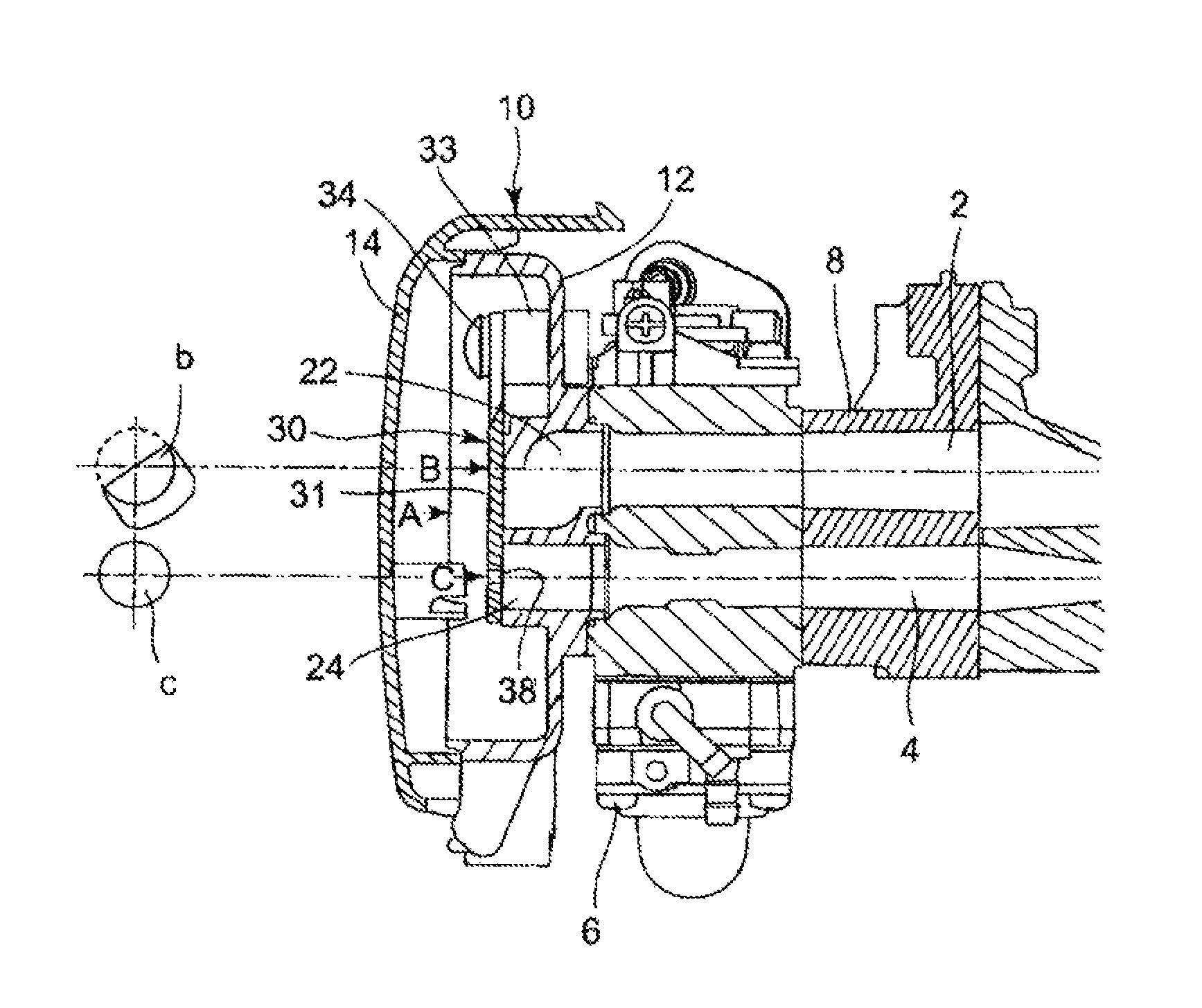
[0027]FIG. 1 is a structural view illustrating the structure of the vicinity of an air cleaner device for two-stroke engines according to one embodiment of the present invention.

[0028]In FIG. 1, reference numeral 6 denotes a carburetor, and 8 denotes an insulator interposed between the carburetor 6 and a cylinder (not shown).

[0029]Reference numeral 2 denotes an air supply passage, configured to communicate an air passage in the carburetor 6 via inside the insulator 8 with a scavenging port (not shown) opened in a side portion of the cylinder and a scavengin...


PUM


Abstract

An air cleaner in a two-stroke engine having an air supply passage and an air / fuel mixture supply passage includes: a first air passage and a second air passage arranged in parallel, the first air passage being communicated with the air supply passage and the second air passage being communicated with the air / fuel mixture supply passage; and a choke valve opening and closing both of the first air passage and the second air passage of the air cleaner. The choke valve has a pivot axis and a pivotable valve member pivoting about the pivot axis to open and close respective inlet openings of the first air passage and the second air passage. One of the first air passage and the second air passage that is located closer to the pivot axis has an inlet opening flattened along a pivoting edge of the valve member.

Description

BACKGROUND OF THE INVENTION[0001]1. Technical Field[0002]The present invention relates to an air cleaner structure in two-stroke engines, and more particularly to an air cleaner structure in a two-stroke engine having an air passage that is connected midway of a scavenging passage communicating a scavenging port with a crank chamber and that supplies leading air from the air cleaner to the scavenging passage, and an air / fuel mixture passage supplying air / fuel mixture created in a carburetor to the crank chamber.[0003]2. Description of the Related Art[0004]A stratified scavenging two-stroke engine includes a scavenging passage communicating a scavenging port provided in a side portion of a cylinder with a crank chamber, an air passage connected midway of the scavenging passage for supplying scavenging air from an air cleaner to the scavenging passage, and an air / fuel mixture passage for supplying air / fuel mixture created in a carburetor to the crank chamber. Prior to supplying the ai...

Claims


Application Information

Patent Timeline
Patent Type & Authority Patents(United States)
IPC IPC(8): F02M17/34F02M35/024F02B25/22F02B25/00F02B75/02F02M1/02
CPCF02B25/22F02M1/02F02B2075/025F02M17/34F02M35/024
Inventor UENOYAMA, KAZUYUKIKIMURA, TAKAHIRO
Owner MITSUBISHI HEAVY IND MEIKI ENGINES CO LTD
Why Eureka
Try Eureka