Cloth surface defect online monitoring device and monitoring method thereof

A surface defect and monitoring device technology, which is applied in measuring devices, optical testing of defects/defects, and material analysis through optical means, and can solve problems such as drastic changes in lighting, missed inspections, and affecting cloth defects

Pending Publication Date: 2020-09-25
圣山集团有限公司
View PDF1 Cites 3 Cited by
  • Summary
  • Abstract
  • Description
  • Claims
  • Application Information

AI Technical Summary

Problems solved by technology

[0004] The invention solves the problems in the prior art that due to the jitter of the cloth, the light changes violently, which affects the judgment of the cloth defect, and there are certain missed and wrong detections, and provides an online monitoring device for the cloth surface defect and its monitoring method

Method used


Image

  • Cloth surface defect online monitoring device and monitoring method thereof
  • Cloth surface defect online monitoring device and monitoring method thereof
  • Cloth surface defect online monitoring device and monitoring method thereof

Examples


Embodiment 1

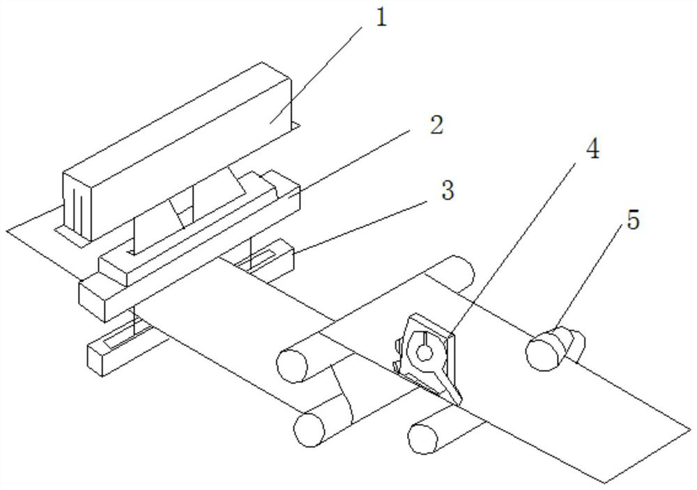
[0034] An online monitoring device for cloth surface defects (see attached Figures 1 to 4 ), configured on the cloth production line through the installation bracket 11, including a computer for identification, a labeling machine 4 for labeling defects, an encoder 5, a positive light source 2, a backlight source 3 and a recognition camera 1, and the positive light source is configured in Above the backlight source, the front light source includes a back-shaped light source platform with a rectangular hole in the center, the light sources of the light source platform are evenly arranged on both sides of the long side of the rectangular hole, and the recognition camera is arranged at the center of the rectangular hole Above, the recognition camera, front light source and backlight form a straight line perpendicular to the cloth, the output end of the recognition camera is electrically connected to the recognition computer, the labeling machine is located behind the recognition c...

Embodiment 2

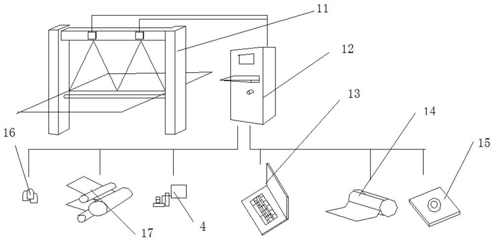
[0042] This embodiment is basically the same as Embodiment 1, the difference is that in this embodiment, the identification computer performs big data collection through a big data acquisition station before performing online monitoring work, and the big data acquisition station includes flawed Cloth, reciprocating conveyor belt 23, front adjustable light source 21, back adjustable light source 22, shaking device 25 and encoder, the encoder is installed on the reciprocating conveyor belt to code and read the transmission distance of the reciprocating conveyor belt, and the recognition camera is installed On the reciprocating conveyor belt, the cloth with defects is installed on the reciprocating conveyor belt, the front adjustable light source, the rear adjustable light source and the recognition camera form a straight line perpendicular to the cloth with defects, and the front The control ends of the adjustable light source and the back adjustable light source are connected to...

Embodiment 3

[0044] A method for on-line monitoring of cloth surface blemishes, suitable for the on-line monitoring device for cloth surface blemishes as described in Example 2,

[0045]Step 1: The cloth production line is running, the light source of the light source table is started, the encoder detects the current transmission speed of the cloth production line, and the identification computer determines the current cloth position according to the encoder data;

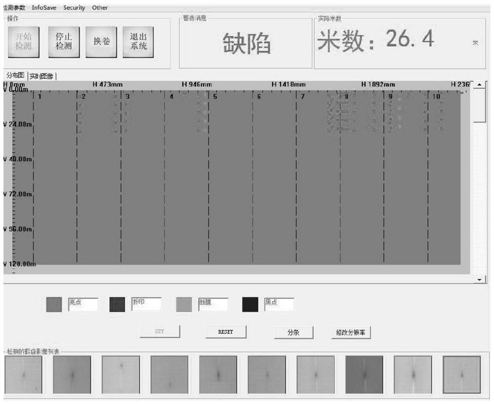
[0046] Step 2: The recognition camera monitors the image of the cloth within the range of the current light source and transmits it to the computer for recognition, and the computer for recognition receives the image information of the cloth;

[0047] Step 3: The computer for identification performs identification according to the predetermined parameters. The identification is divided into normal and defective states. If there is a defect, the computer for identification will send a control command to the labeling machine, and ...


PUM


Abstract

The invention relates to a cloth surface defect online monitoring device. The problems in the prior art are solved. Key points of the technical scheme are as follows: the device is arranged on a clothproduction line, the device comprises a computer for identification, a labeling machine for marking defective labels, an encoder, a front light source, a backlight source and an identification camera, the front light source is arranged above the backlight source, the front light source comprises a concentric-square-shaped light source table with a rectangular hole in the center, light sources ofthe light source table are evenly arranged on the two sides of the long edge of the rectangular hole. The identification camera is arranged above the rectangular hole; the identification camera, the front light source and the backlight source form a straight line vertical to the cloth; the output end of the identification camera is electrically connected with the computer for identification, the labeling machine is located behind the identification camera, the action end of the labeling machine is aligned with cloth, the control end of the labeling machine is connected with the computer for identification, the encoder is used for detecting the transmission speed of the current cloth, and the output end of the encoder is connected with the computer for identification.

Description

technical field [0001] The invention belongs to cloth quality inspection equipment, and relates to an online monitoring device and a monitoring method for cloth surface blemishes. Background technique [0002] At present, it is a very normal thing to have defects in cloth printing and dyeing production. In the past, the defects of cloth were detected by the visual inspection of quality inspectors. The detection was difficult and relied on personal experience. Therefore, it was gradually replaced by computer-aided identification. However, although the efficiency of computer-aided recognition has been greatly improved, but under the influence of the angle of light, the judgment of many suspected defects will still rely on the personal experience of the quality inspector. Therefore, it is necessary to develop a cloth with higher efficiency. An on-line monitoring device for surface defects and a monitoring method thereof are imperative. [0003] Chinese Patent Publication No.: ...

Claims


Application Information

Patent Timeline
Patent Type & Authority Applications(China)
IPC IPC(8): G01N21/89G01N21/01
CPCG01N21/01G01N21/89G01N2021/0112
Inventor 许尔明
Owner 圣山集团有限公司
Why Eureka
Try Eureka