Piezoelectric motor, drive unit, electronic part transfer apparatus, electronic part inspection apparatus, robot, and printer

a technology of electronic parts and drives, applied in piezoelectric/electrostriction/magnetostriction machines, piezoelectric/electrostriction device details, gripping heads, etc., can solve the problems of poor abrasion resistance of silicon nitride, for example, inferior to aluminum oxide in abrasion resistance, etc., to achieve effective restraint of sliding movement with respect to each other, the effect of cutting a printed printing medium smoothly

Active Publication Date: 2016-05-03
SEIKO EPSON CORP
View PDF45 Cites 0 Cited by
  • Summary
  • Abstract
  • Description
  • Claims
  • Application Information

AI Technical Summary

Benefits of technology

[0009]According to the piezoelectric motor of this application example, the values of the Young's moduli of the driving projection and the driven member which come into abutment and slide with each other are differentiated. The material having a large value of Young's modulus tends to have large value of plastic deformation hardness (Vickers hardness) as well, but these values are not necessarily proportional. Therefore, for example, even two of the driven members are formed of materials having almost the same plastic deformation hardness, the driven member formed of a material having a high Young's modulus is subject to smaller amount of indentation on the surface of the material due to the abutment with the driving projection in comparison with the driven member formed of a material having a low Young's modulus. When the driving projection was brought into abutment with and slid with respect to the driven member, it was found that the driven member formed of the material having a higher Young's modulus was subject to less indentation and hence was subject to less abrasion caused by a sliding motion, and hence was superior in abrasion resistance. In this manner, in the relationship between the driving projection and the driven member of the piezoelectric motor, the Young's modulus in the vicinity of the surface portions thereof which come into abutment and slide with each other affects on the abrasion resistance. In addition, it was found that silicon nitride, for example, is inferior in abrasion resistance in comparison with aluminum oxide if the Young's modulus of the outermost surface thereof is lower than that of the aluminum oxide even though the plastic deformation hardness thereof is higher than that of aluminum oxide. The Young's modulus in this case is a value within a minute range in the vicinity of the surface portion which cannot be measured accurately by measurement of Vickers hardness, which is plastic deformation hardness. In the light of such situation, the piezoelectric motor is characterized by having the relationship between the Young's modulus E1 of the driving projection and the Young's modulus E2 of the driven member of E1≠E2 in addition to the plastic deformation of the related art as a relationship between the driving projection and the driven member. The piezoelectric motor having the characteristic as described above allows improvement of the abrasion resistance of the driving projection and the driven member and, simultaneously, easy setting or the like which causes one of the driving projection and the driven member to be abraded is enabled. Accordingly, the piezoelectric motor may include the driving projection and the driven member having optimal abrasion resistance in accordance with the required function.Application Example 2
[0028]According to the printer of this application example, the mechanism of the piezoelectric motor or the mechanism equivalent to the piezoelectric motor, that is, the piezoelectric element, the oscillating portion having the piezoelectric elements laminated one on top of another, the driving projection provided at an end of the oscillating portion, and the driven member driven by abutment with the driving projection are provided. This printer has a configuration in which the driving projection and the driven member driven by the driving projection drive a cutter or the like configured to cut a printed printing medium smoothly, and the driving projection and the driven member have different Young's moduli, and hence the abrasion caused by the sliding movement with respect to each other may effectively be restrained.

Problems solved by technology

Therefore, there is a problem that effective restraint of the abrasion caused by the sliding motion is difficult only by setting the hardness on the basis of the plastic deformation hardness as described in JP-A-2004-236493 and JP-A-2007-306799.
In addition, it was found that silicon nitride, for example, is inferior in abrasion resistance in comparison with aluminum oxide if the Young's modulus of the outermost surface thereof is lower than that of the aluminum oxide even though the plastic deformation hardness thereof is higher than that of aluminum oxide.

Method used


Image

  • Piezoelectric motor, drive unit, electronic part transfer apparatus, electronic part inspection apparatus, robot, and printer
  • Piezoelectric motor, drive unit, electronic part transfer apparatus, electronic part inspection apparatus, robot, and printer
  • Piezoelectric motor, drive unit, electronic part transfer apparatus, electronic part inspection apparatus, robot, and printer

Examples


first embodiment

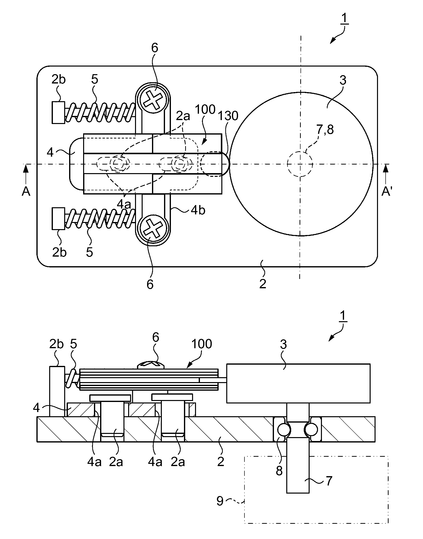
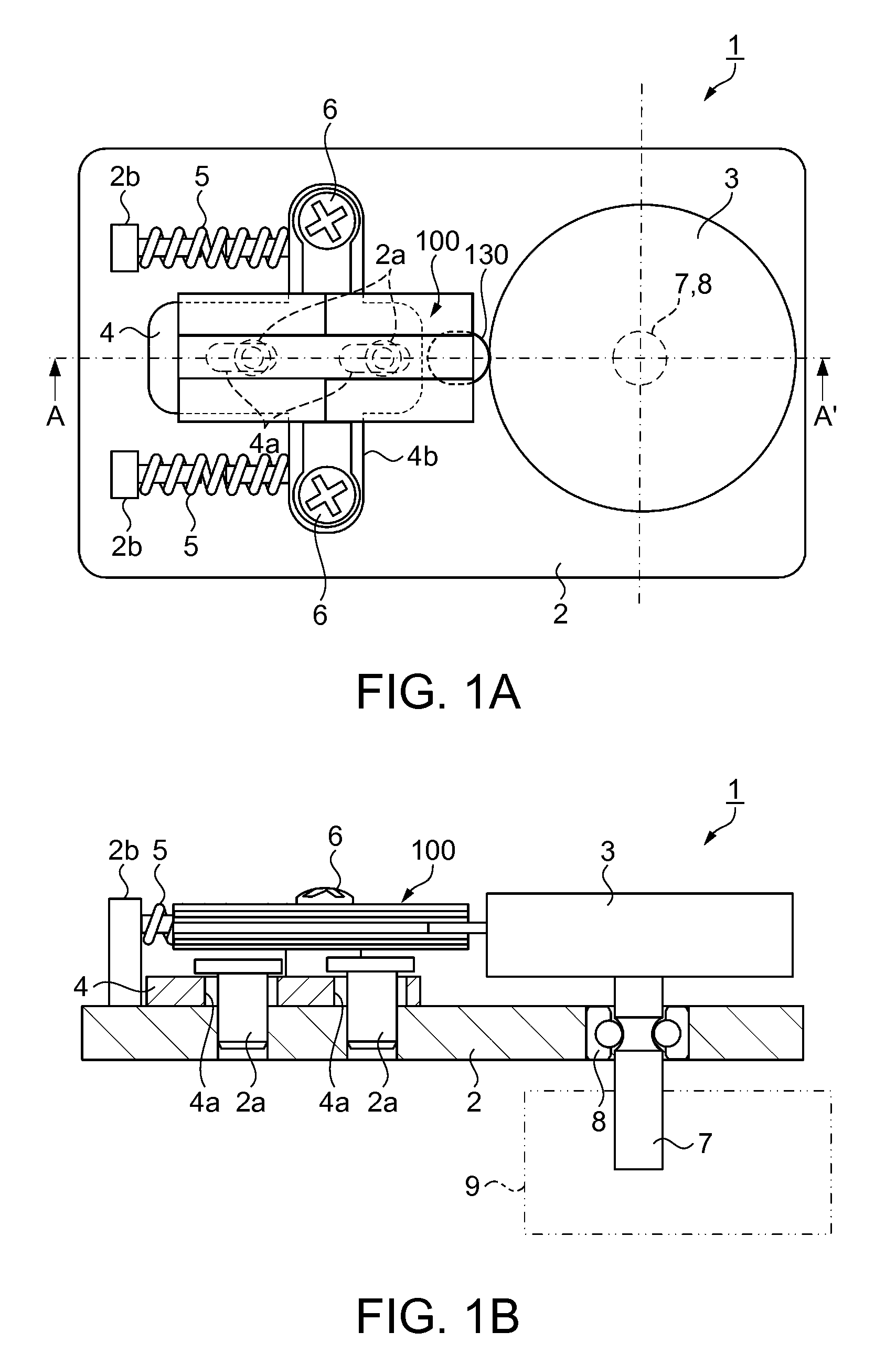
[0055]FIG. 1A is a plan view illustrating the piezoelectric motor of a first embodiment, and FIG. 1B is a cross-sectional view illustrating the piezoelectric motor taken along the line A-A′ in FIG. 1A. As illustrated in FIG. 1A, a piezoelectric motors 1 includes a base 2, a driven member 3 rotatably provided on the base 2, a supporting member 4 slidably fixed to the base 2, coil springs 5 configured to urge the supporting member 4 toward the driven member 3, and a piezoelectric actuator 100 fixed to the supporting member 4 with screws 6.

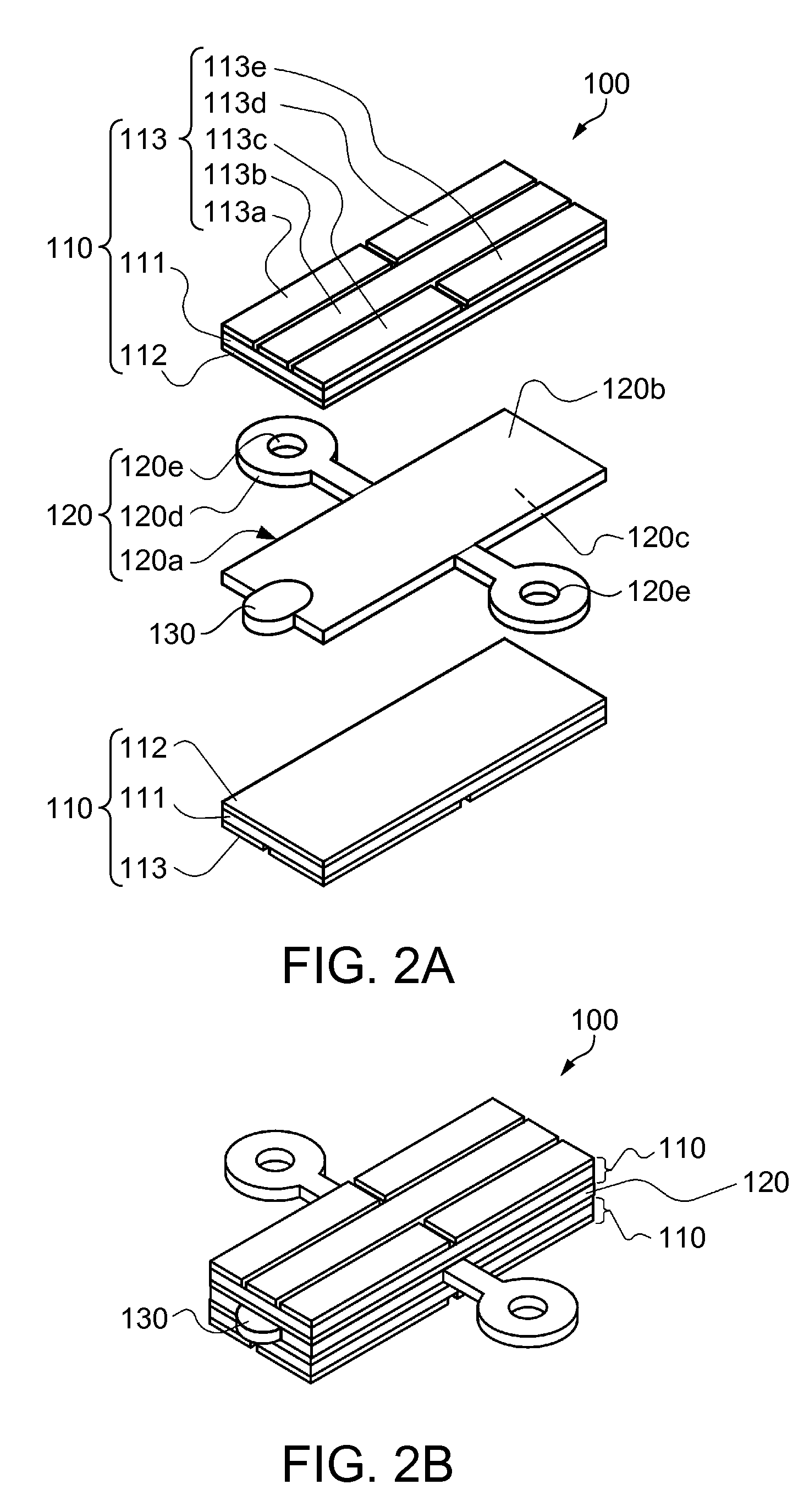
[0056]First of all, the piezoelectric actuator 100 of the piezoelectric motor 1 will be described. FIG. 2A is a perspective view illustrating a configuration of a piezoelectric actuator, and FIG. 2A is a perspective view illustrating an appearance of the piezoelectric actuator.

[0057]The piezoelectric actuator 100 is formed by laminating piezoelectric elements 110 on one surface 120b and a back surface 120c of a plate shaped oscillating plate (oscilla...

second embodiment

[0070]Subsequently, a mechanism of the piezoelectric motor 1, that is, a drive unit provided with the piezoelectric elements 110, the oscillating plate 120, the driving projection 130, and a driven member driven by the driving projection 130 will be described. FIG. 6A is a plan view illustrating the drive unit according to a second embodiment, and FIG. 6B is a cross-sectional view illustrating the drive unit.

[0071]As illustrated in FIGS. 6A and 6B, a drive unit 20 includes a base 21, the supporting member 4 fixed to the base 21, the piezoelectric actuator 100 provided on the supporting member 4 and including the driving projection 130, and a driven member 25 to be driven by the abutment with the driving projection 130. The driven member 25 has a ring shape having an inner peripheral surface 25a which comes into abutment with the driving projection 130. The inner peripheral surface 25a of the driven member 25 is formed to be depressed in the direction of diameter thereof. The driven ...

third embodiment

[0072]Subsequently, the mechanism of the piezoelectric motor 1, that is, an electronic part inspection apparatus provided with the piezoelectric elements 110, the oscillating plate 120, the driving projection 130, and the driven member driven by the driving projection 130 will be described. FIG. 7 is a perspective view illustrating the electronic part inspection apparatus according to a third embodiment, and FIG. 8 is a perspective view illustrating a correcting mechanism portion of the electronic part inspection apparatus. As illustrated in FIG. 7, an electronic part inspection apparatus 30 includes a parallelepiped base 31 and a control apparatus 38 configured to control the electronic part inspection apparatus 30 on a side portion of the base 31. Here, the longitudinal direction of the base 31 is defined as a Y-direction (lateral direction) and a direction orthogonal to the Y-direction on a horizontal plane is defined as an X-direction (fore-and-aft direction), and the vertical d...


PUM


Abstract

A piezoelectric motor includes a piezoelectric element, an oscillating plate including the piezoelectric element, a driving projection provided at an end of the oscillating plate, and a driven member driven by the driving projection coming into abutment therewith and is characterized in that Young's modulus E1 of the driving projection and Young's modulus E2 of the driven member are different.

Description

BACKGROUND[0001]1. Technical Field[0002]The present invention relates to a piezoelectric motor which utilizes the oscillation of a piezoelectric body, a drive unit provided with a mechanism of the piezoelectric motor, an electronic part transfer apparatus, an electronic part inspection apparatus, a robot, and a printer.[0003]2. Related Art[0004]In the related art, an ultrasonic motor on which a piezoelectric actuator having a piezoelectric ceramics board and a pressing member is mounted as described in JP-A-2004-236493 is disclosed as a piezoelectric motor. The ultrasonic motor has a configuration in which the pressing member performs an oval motion by the oscillation of the piezoelectric ceramics board. The ultrasonic motor is configured to move a movable member (stage) in abutment with the pressing member along a guide rail by the oval motion of the pressing member. In this case, hardness H1 of an abutting portion of the pressing member and hardness H2 of an abutting portion of th...

Claims


Application Information

Patent Timeline
Patent Type & Authority Patents(United States)
IPC IPC(8): H01L41/09H01L41/04H02N2/10B25J15/00H02N2/12H02N2/00H02N2/16
CPCH01L41/09H01L41/04H02N2/004H02N2/007B25J15/0009H02N2/103H02N2/126H02N2/0095H02N2/163H10N30/20H10N30/80
Inventor KAMIJO, KOICHITSUCHIYA, KAZUHIRO
Owner SEIKO EPSON CORP
Why Eureka
Try Eureka