Piezoelectric motor, drive unit, electronic part transfer apparatus, electronic part inspection apparatus, robot, and printer
a technology of electronic parts and drives, applied in the direction of piezoelectric/electrostrictive device details, device details, manufacturing tools, etc., can solve the problems of poor abrasion resistance of silicon nitride, for example, inferior to aluminum oxide in abrasion resistance, and achieve the effect of effectively restrainting the sliding movement with respect to each other and cutting smoothly
- Summary
- Abstract
- Description
- Claims
- Application Information
AI Technical Summary
Benefits of technology
Problems solved by technology
Method used
Image
Examples
first embodiment
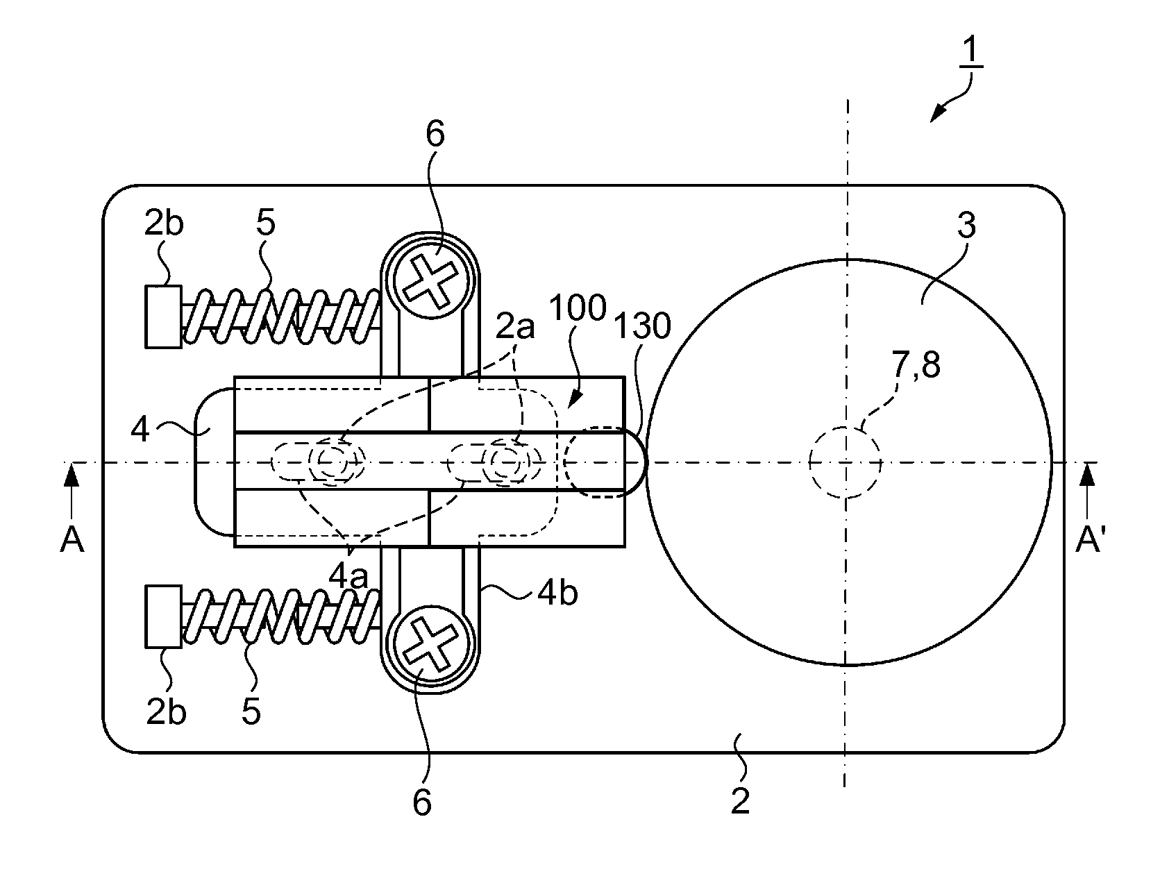
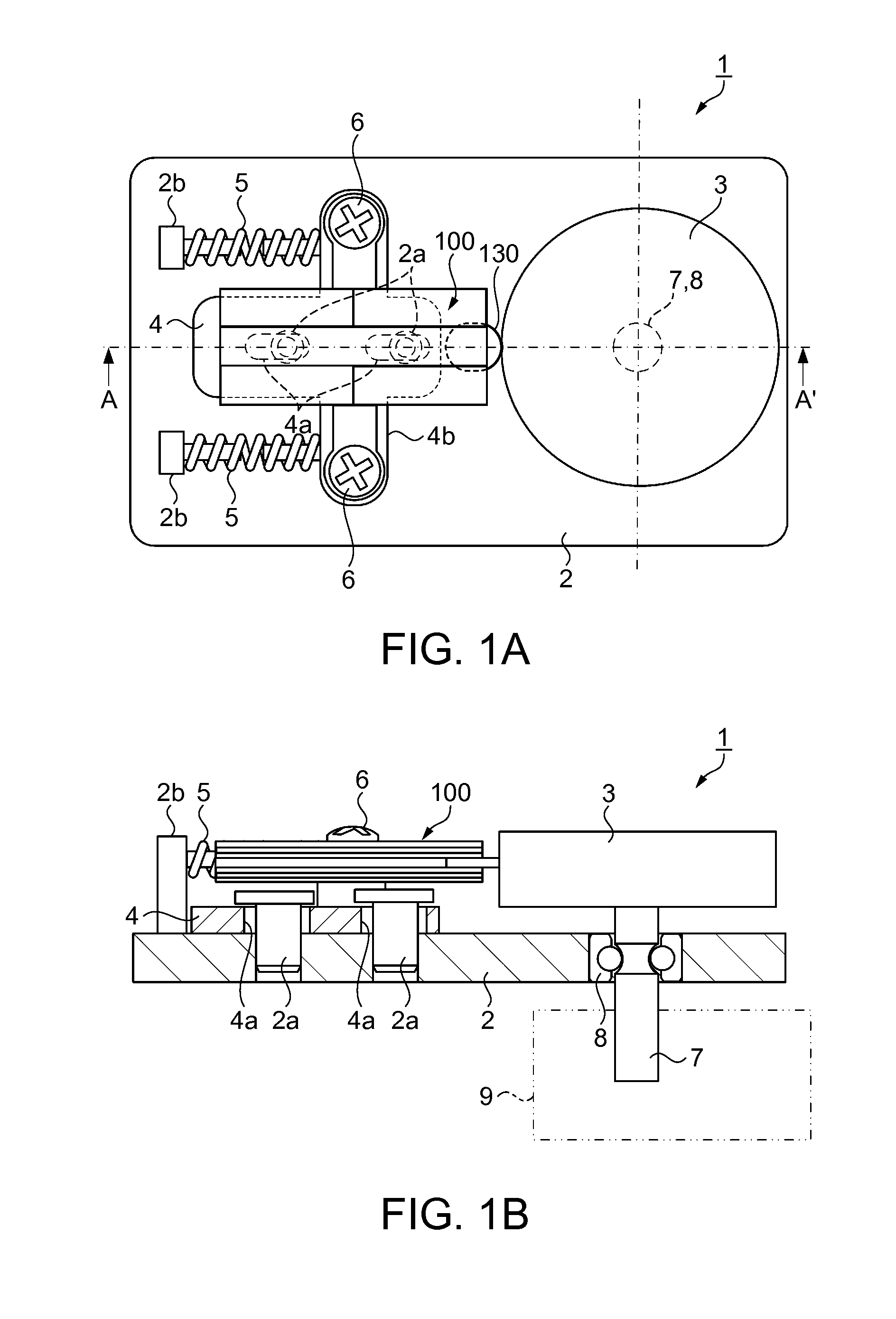
[0055]FIG. 1A is a plan view illustrating the piezoelectric motor of a first embodiment, and FIG. 1B is a cross-sectional view illustrating the piezoelectric motor taken along the line A-A′ in FIG. 1A. As illustrated in FIG. 1A, a piezoelectric motors 1 includes a base 2, a driven member 3 rotatably provided on the base 2, a supporting member 4 slidably fixed to the base 2, coil springs 5 configured to urge the supporting member 4 toward the driven member 3, and a piezoelectric actuator 100 fixed to the supporting member 4 with screws 6.
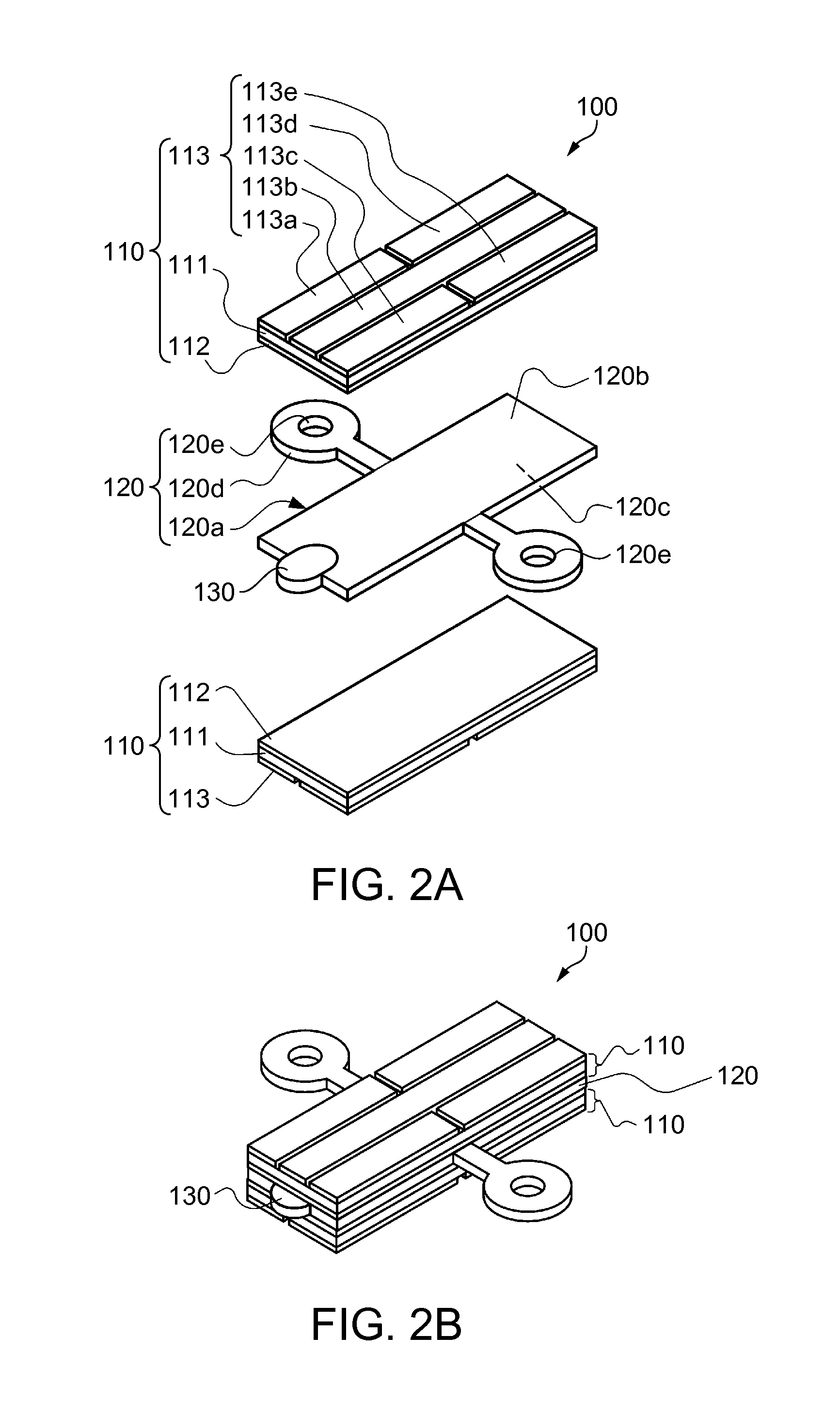
[0056]First of all, the piezoelectric actuator 100 of the piezoelectric motor 1 will be described. FIG. 2A is a perspective view illustrating a configuration of a piezoelectric actuator, and FIG. 2A is a perspective view illustrating an appearance of the piezoelectric actuator.
[0057]The piezoelectric actuator 100 is formed by laminating piezoelectric elements 110 on one surface 120b and a back surface 120c of a plate shaped oscillating plate (oscilla...
second embodiment
[0070]Subsequently, a mechanism of the piezoelectric motor 1, that is, a drive unit provided with the piezoelectric elements 110, the oscillating plate 120, the driving projection 130, and a driven member driven by the driving projection 130 will be described. FIG. 6A is a plan view illustrating the drive unit according to a second embodiment, and FIG. 6B is a cross-sectional view illustrating the drive unit.
[0071]As illustrated in FIGS. 6A and 6B, a drive unit 20 includes a base 21, the supporting member 4 fixed to the base 21, the piezoelectric actuator 100 provided on the supporting member 4 and including the driving projection 130, and a driven member 25 to be driven by the abutment with the driving projection 130. The driven member 25 has a ring shape having an inner peripheral surface 25a which comes into abutment with the driving projection 130. The inner peripheral surface 25a of the driven member 25 is formed to be depressed in the direction of diameter thereof. The driven ...
third embodiment
[0072]Subsequently, the mechanism of the piezoelectric motor 1, that is, an electronic part inspection apparatus provided with the piezoelectric elements 110, the oscillating plate 120, the driving projection 130, and the driven member driven by the driving projection 130 will be described. FIG. 7 is a perspective view illustrating the electronic part inspection apparatus according to a third embodiment, and FIG. 8 is a perspective view illustrating a correcting mechanism portion of the electronic part inspection apparatus. As illustrated in FIG. 7, an electronic part inspection apparatus 30 includes a parallelepiped base 31 and a control apparatus 38 configured to control the electronic part inspection apparatus 30 on a side portion of the base 31. Here, the longitudinal direction of the base 31 is defined as a Y-direction (lateral direction) and a direction orthogonal to the Y-direction on a horizontal plane is defined as an X-direction (fore-and-aft direction), and the vertical d...
PUM
 Abstract
Description
Claims
Application Information
 - R&D
- Intellectual Property
- Life Sciences
- Materials
- Tech Scout
- Unparalleled Data Quality
- Higher Quality Content
- 60% Fewer Hallucinations
Browse by: Latest US Patents, China's latest patents, Technical Efficacy Thesaurus, Application Domain, Technology Topic, Popular Technical Reports.
© 2025 PatSnap. All rights reserved.Legal|Privacy policy|Modern Slavery Act Transparency Statement|Sitemap|About US| Contact US: help@patsnap.com


