
Noise filter device

a filter device and noise technology, applied in the direction of impedence networks, multiple-port networks, electrical devices, etc., can solve the problems of deteriorating filter characteristics, adversely affecting other elements, and complicating the device configuration, so as to prevent a short circuit and avoid a short circuit

Active Publication Date: 2016-05-03
AUTONETWORKS TECH LTD +2
View PDF2 Cites 3 Cited by
  • Summary
  • Abstract
  • Description
  • Claims
  • Application Information

AI Technical Summary

Benefits of technology

The patent describes a noise filter device that includes an inductance coil and a bracket. To prevent a short circuit, an insulating spacer is used between the inductance coil and the bracket. The bracket is recessed in a groove on the surface of the housing to prevent unintended contact and a short circuit. The device also includes gaps between the inductance coil and the bracket to form a closed magnetic path and suppress magnetic flux saturation and noise filter characteristics. The bracket is at least partially exposed, improving wiring flexibility and facilitating layout design.

Problems solved by technology

However, magnetic fluxes generated by a current flowing in the coil may adversely affect other elements and deteriorate filter characteristics.
However, the bracket must be exposed from the bottom surface of the housing when performing wiring to the bracket, thereby complicating a device configuration.

Method used


Image

  • Noise filter device
  • Noise filter device
  • Noise filter device

Examples


first embodiment

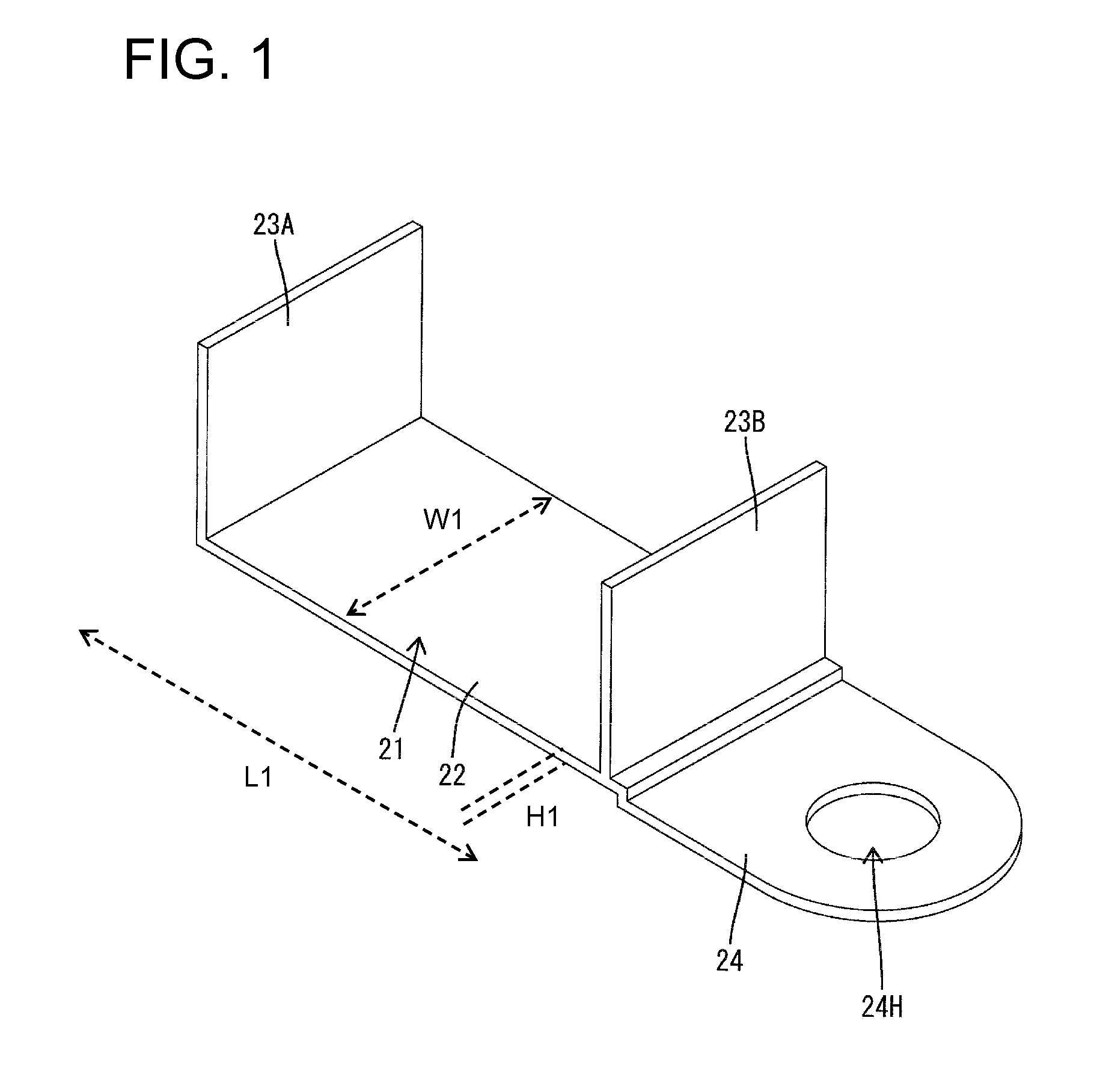
[0020]A noise filter device of a first embodiment includes a bracket 21, an inductance 31 (e.g. coil), a capacitance comprising two capacitors 41, two wires WH that function as input and output terminals, a spacer 61 and a housing 11 for housing the above-described. In the following description, lower and upper sides of FIG. 3 are referred to respectively as front and rear ends concerning a front-back direction.

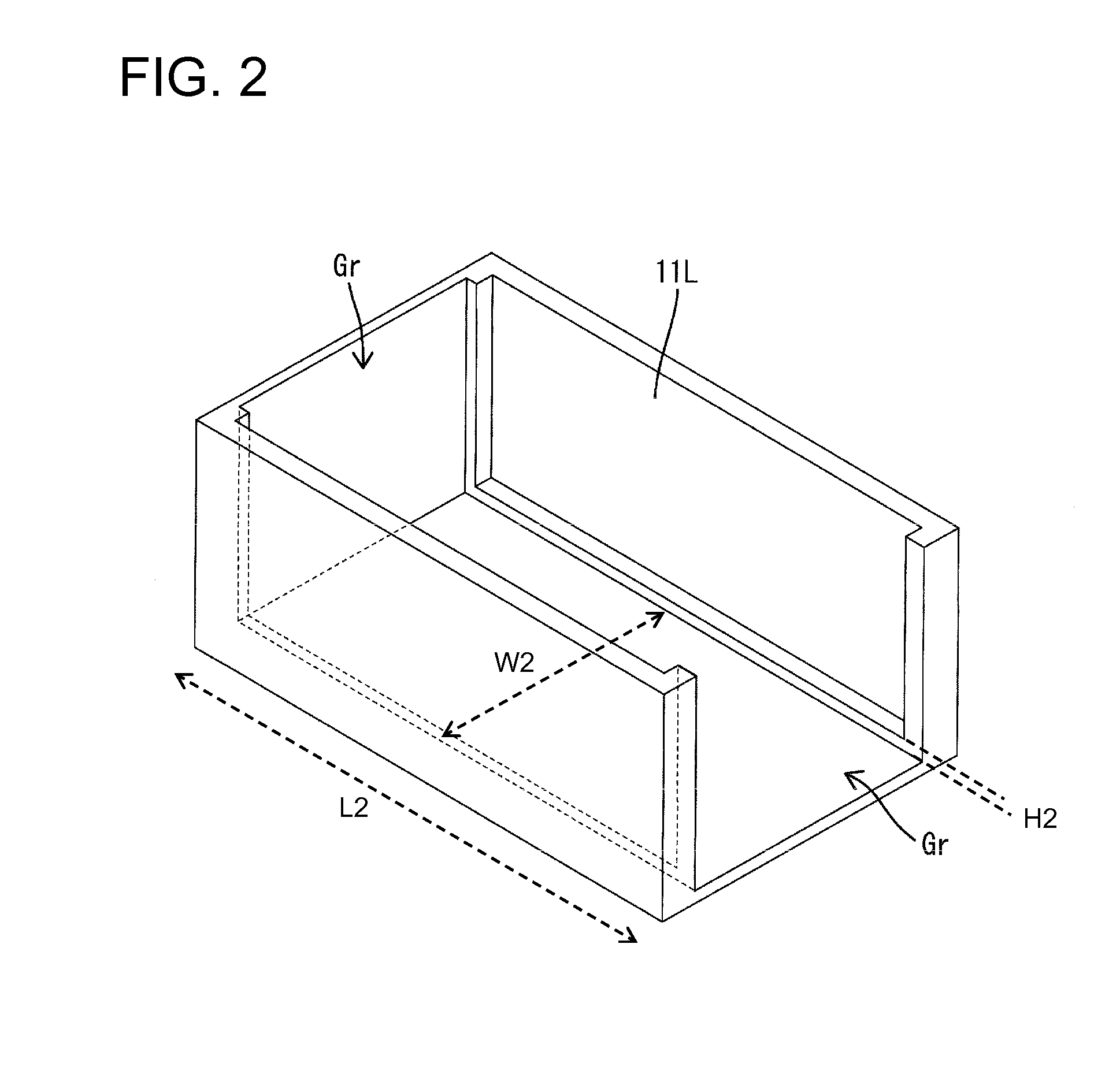
[0021]The housing 11 is made e.g. of synthetic resin and comprises a first or lower housing 11L and a second or upper housing 11U. The first housing 11L defines a substantially box shape with lateral openings. The second housing 11U is capable of at least partly closing the lateral openings as shown in FIG. 3. Two insertion holes 11H are formed in the front surface of the first housing 11L and the wires WH are respectively insertable therein. Further, a laterally extending groove Gr is recessed in a bottom surface of the first housing 11L, as shown in FIG. 2. Further, a verti...

second embodiment

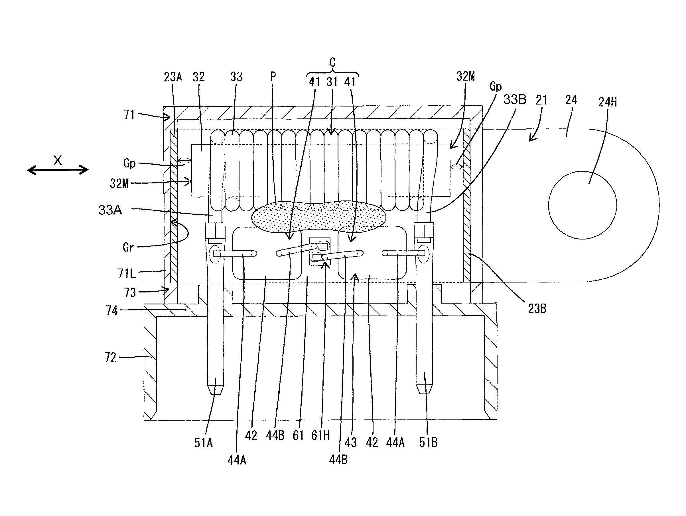
[0036]the noise filter device of the invention is applied to a connector and includes a bracket 21, an inductance 31 comprising a coil 31, two capacitors 41, a spacer 61, a housing 71 and busbar terminal fittings 51A, 51B that function as input and / or output terminals. In the following description, lower and upper sides of FIG. 6 are referred to as front and rear ends concerning the front-back direction.

[0037]The housing 71 is composed of a lower housing 71L in the form of a box with upper, left and front openings and an upper housing 71U capable of at least partly closing the upper and left openings. The united housing 71 is partitioned into a receptacle 72 and a filter housing 73. The receptacle 72 is a rectangular tube that can fit to an unillustrated mating connector.

[0038]As shown in FIG. 6, two tab-shaped busbar terminals 51A, 51B made of copper alloy are fixed by insert molding to a partition wall 74 between the receptacle 72 and the filter housing 73. Tip parts of the busbar...


PUM


Abstract

A noise filter device has a coil formed by winding a conductive wire on a magnetic core. The noise filter device further has a bracket formed of a magnetic material and grounded. The bracket has a bottom plate and two end plates that project from the bottom plate. The end plates face opposite end surfaces of the magnetic core with predetermined gaps defined between the end plates and the end surfaces. The noise filter device further has capacitors that form part of a noise filter circuit together with the coil and that are connected to the bracket. A housing houses the coil, the capacitors and the bracket in an at least partly exposed state, and input and output terminals are provided for the noise filter circuit.

Description

BACKGROUND OF THE INVENTION[0001]1. Field of the Invention[0002]The invention relates to a noise filter device.[0003]2. Description of the Related Art[0004]A known vehicle-mounted noise filter device includes a filter circuit using a coil and a capacitor that are mounted in a housing. However, magnetic fluxes generated by a current flowing in the coil may adversely affect other elements and deteriorate filter characteristics. US2009 / 115551 discloses a noise filter device with a bracket made of a magnetic material. The bracket has two end plates facing opposite end surfaces of a magnetic core of the coil in an axial direction and a bottom plate is provided in a bottom part of the housing and couples the end plates. With this configuration, magnetic fluxes generated by the flow of a current in the coil are concentrated on a loop magnetic path (closed magnetic path) formed by the magnetic core and the bracket. Thus, magnetic fluxes do not affect other elements.[0005]However, the bracke...

Claims


Application Information

Patent Timeline
Patent Type & Authority Patents(United States)
IPC IPC(8): H03H7/01H03H1/00
CPCH03H7/0115H03H1/0007H03H7/0138
Inventor AIZAWA, TAKESHI
Owner AUTONETWORKS TECH LTD
Learn More