Method and device for bonding parts to be joined, as well as component

a technology of bonding parts and components, applied in the field of method and device for bonding parts to be joined, as well as components, can solve the problems of high labor intensity, high cost, and high cost of riveting methods, and achieves optimized weight, short cycle time, and high joining seam strength.

Active Publication Date: 2016-05-10
AIRBUS OPERATIONS GMBH
View PDF16 Cites 3 Cited by
  • Summary
  • Abstract
  • Description
  • Claims
  • Application Information

AI Technical Summary

Benefits of technology

[0004]It is the objective of the invention to develop a method for producing a bonded joint between fiber-reinforced thermoplastic parts to be joined that eliminates the above-described disadvantages and allows short cycle times. The invention furthermore aims to develop a device for carrying out such a method, as well as a joined component with optimized weight and high joining seam strength.
[0007]Friction stir welding makes it possible to realize short cycle times because elaborate preparatory or follow-up measures such as drilling and cleaning are eliminated after the alignment of the parts to be joined relative to one another. In this case, the friction stir welding can be conveniently automated such that a high reproducible joining seam quality and process quality is ensured in addition to short cycle times. Due to the elimination of rivet bores, friction stir welding furthermore is not associated with structural weakening as it is the case with riveting methods. Elaborate cleaning of adherends is also eliminated. The butt joint does not result in an overlap between the parts to be joined such that a load flow without steps can adjust over the joining seam between the parts to be joined. Furthermore, an elaborate tolerance compensation of the parts to be joined by means of spacers, shims and the like is not required. Consequently, no tensions caused by deformations or distortions of the parts to be joined are introduced into the joining seam. The supplied fiber-containing plastic material causes a thickening of the joining zone such that the parts to be joined are bonded to one another over a larger seam cross section and the seam strength is correspondingly increased, wherein embrittlement of the joining seam is prevented by the fibers such that the joining seam and therefore the joined component have, in principle, the same strength as the parts to be joined.
[0013]The plastic material may also be heated above its melting temperature such that additional heat can be supplied to the joining zone. Heat can be centrally supplied into the joining zone at a distance from the surface by means of the plastic material, particularly if the plastic material is injected between the parts to be joined. In this case, a contact pressure of the friction shoulder can possibly be reduced.
[0018]An inventive component is manufactured in accordance with an inventive method and therefore characterized by a high-strength and high-quality joining seam, a high structural stability, a load-optimized and weight-optimized lightweight construction and a load flow without steps over the region of the seam.

Problems solved by technology

However, epoxy resins are thermosetting plastics and therefore not fusible after curing such that the plastic-based parts are joined with joining methods known from metal constructions such as riveting or bonding.
Due to rivet bores, however, riveting methods are associated with a structural weakening that can be intensified by torn fibers, delaminations and the like.
In addition, riveting methods are very time-consuming due to the plurality of individual steps to be carried out manually such as aligning the parts to be joined relative to one another, producing the rivet bores, cleaning the rivet bores, tacking and setting the rivets.
Furthermore, quasi-isotropic properties of the parts to be joined are not utilized during the riveting process, but rather annihilated in certain areas.
The adhesives also require a certain curing time such that bonding methods are also time-consuming.
In addition, it is not possible to carry out a non-destructive examination of the bond.
Riveting methods and known bonding methods also require a material overlap such that the finished component is not optimized with respect to its weight on the one hand and a steplike load flow is created on the other hand.

Method used


Image

  • Method and device for bonding parts to be joined, as well as component
  • Method and device for bonding parts to be joined, as well as component
  • Method and device for bonding parts to be joined, as well as component

Examples


Embodiment Construction

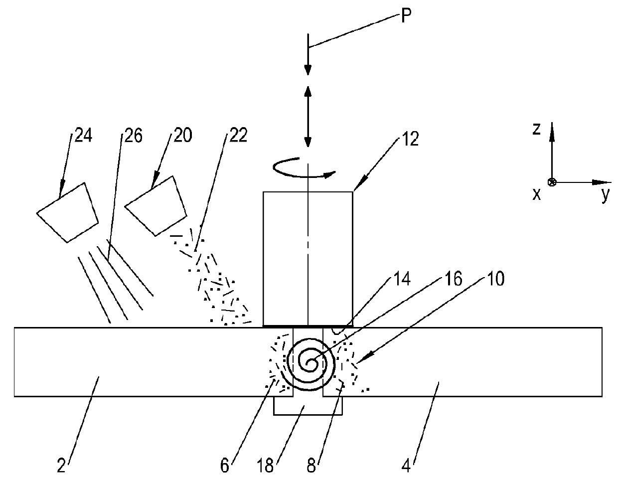
[0025]FIG. 1 shows a first device 1 and a first method for bonding two parts to be joined 2, 4 into a component.

[0026]The parts to be joined 2, 4 are positioned in the form of a butt joint and form a joining zone 10 with their opposing and contacting body sections 6, 8. For example, the parts to be joined 2, 4 form skin panels for aircraft fuselages that need to be joined to one another. The parts to be joined 2, 4 consist of fiber-reinforced laminates with a plurality of fiber structures such as non crimp fiber fabrics, woven fiber fabrics, prepregs and the like that are arranged in a layered fashion and embedded in a thermoplastic matrix. The fibers of the fiber structures consist of carbon fibers, glass fibers, aramid fibers and the like that are realized in the form of long fibers.

[0027]The device 1 has a friction stir tool 12 with a friction shoulder 14 and with a stirring pin 16. The friction shoulder 14 and the stirring pin 16 are able to rotate in the same direction about a ...


PUM

PropertyMeasurementUnit
melting temperatureaaaaaaaaaa
plasticaaaaaaaaaa
temperatureaaaaaaaaaa

Abstract

A method is provided for producing a bonded joint between fiber-reinforced thermoplastic parts to be joined, in which fiber-containing plastic material is mixed into the joining zone while friction stir welding the parts to be joined in the form of a butt joint. A device for carrying out such a method for a joined component is also provided.

Description

TECHNICAL FIELD[0001]The invention pertains to a method for producing a bonded joint between fiber-reinforced thermoplastic parts to be joined, a device for carrying out such a method and a component manufactured in accordance with such a method.BACKGROUND OF RELATED ART[0002]Civil aircraft are traditionally manufactured in the form of metal constructions. In recent times, however, aircraft parts or parts to be joined such as fuselage shells, circumferential reinforcements, longitudinal reinforcements, crossbeams, wing and tail unit shells and the like are increasingly manufactured of fiber-reinforced plastics. These plastics contain, for example, carbon fibers, aramid fibers or glass fibers that are arranged in a plurality of layers and embedded in an epoxy resin matrix. However, epoxy resins are thermosetting plastics and therefore not fusible after curing such that the plastic-based parts are joined with joining methods known from metal constructions such as riveting or bonding. ...

Claims


Application Information

Patent Timeline
Patent Type & Authority Patents(United States)
IPC IPC(8): B29C65/06B23K20/12B29C35/02B29C65/00B29C65/08B29C65/02B29L31/30
CPCB29C65/0681B23K20/128B23K20/1255B29C66/1142B29C66/721B29C66/72143B29C66/73921B23K2201/08B23K2201/18B23K2203/16B29C35/02B29C65/028B29C65/06B29C65/0672B29C65/086B29C66/0242B29C66/0382B29C66/7212B29C66/72141B29C66/7394B29C66/836B29C66/9261B29L2031/3082Y10T428/24479B29K2307/04B29K2309/08B29K2277/10B29C66/43B29C65/4815B29C65/72B29C66/30341B29C65/488B23K2101/08B23K2101/18B23K2103/16B23K20/122B29K2101/12B29K2105/08B29K2105/256
Inventor GOEHLICH, ROBERT ALEXANDERSANDER, MALTE
Owner AIRBUS OPERATIONS GMBH
Why Eureka
Try Eureka