Imaging apparatus

a technology apparatus, which is applied in the field of image stabilizing system, can solve the problems of difficult to secure a sufficient space, difficult to achieve the effect of ensuring a sufficient space, and small siz

Active Publication Date: 2016-05-10
HOYA CORP
View PDF48 Cites 3 Cited by
  • Summary
  • Abstract
  • Description
  • Claims
  • Application Information

AI Technical Summary

Benefits of technology

[0014]Accordingly, the present invention provides an imaging apparatus equipped with an image-stabilizing system which is small in size and superior in anti-shake capability.
[0022]If the arrangement of the permanent magnet satisfies the above specified conditions, the stability and accuracy of the spherically swinging operation can be improved, while variations in the distance (gap) between the permanent magnet and the coil can be suppressed. If the distance γ1 is equal to zero and / or the distance γ2 is equal to zero, the center of the outer profile of the permanent magnet is arranged on a tangent point of the imaginary sphere, further increasing the effects of stability and accuracy of the spherically swinging operation and the suppression of variations in the distance (gap) between the permanent magnet and the coil.
[0026]According to the present invention, an imaging apparatus equipped with an image-stabilizing system which is slim in the forward / rearward direction (with the direction toward an object to be photographed set to correspond to the forward direction) and superior in image-stabilizing capability is obtained due to the structure in which the front lens element, which is an element of the front lens group that constitutes a bending optical system and positioned in front of the reflector element, is made to spherically swing about the spherical-swinging center to perform an image-stabilizing operation. Since the center of the spherical motion is set at a position on an extension of the optical axis, of the front lens element, which extends away from the back side of a reflection surface of the reflector element, the support mechanism for the movable frame that holds the front lens element can be constructed in a space-efficient manner. Additionally, as for the actuator, which makes the movable frame that holds the front lens element spherically swing about the spherical-swinging center, the actuator can be structured to be superior in accuracy and stability of image-stabilizing driving of the movable frame and also in space-utilization. Hence, an imaging apparatus equipped with an image-stabilizing system which is small in size and superior in image-stabilizing capability is obtained.

Problems solved by technology

However, movements of an optical element to reduce image shake (image-stabilizing optical element) exert an adverse influence on the optical performance such as aberrations, and a space corresponding to the moving amount of the optical element is required.
In the first type of image-stabilizing system, a substrate which is connected to the image sensor moves while following the image sensor; accordingly, the peripheral electrical components, in addition to the image sensor, need to be designed so as to be compatible with such movements, so that the image-stabilizing system tends to be complicated in structure and high in production cost.
In addition, although the periphery of the imaging surface of the image sensor needs to have a dust-resistant structure, it is difficult to secure a sufficient space which allows the image sensor to perform an image-stabilizing operation while maintaining a dust-resistant structure within a small imaging unit intended to be incorporated in a cellular phone or a smart device.
In the second type of image-stabilizing system, the moving direction of the image-stabilizing lens during an image-stabilizing operation corresponds to the thickness direction of the imaging unit (the forward / rearward direction with the direction toward an object to be photographed set to correspond to the forward direction), so that a problem occurs with it being difficult to incorporate the image-stabilizing system into the thin imaging unit because the internal space thereof is limited.
Conversely, if this type of image-stabilizing system is used, reduction in thickness of the imaging unit becomes limited.
A similar problem exists in the type of image-stabilizing system which moves an image sensor, not a lens element, in the thickness direction of the imaging unit.
In the third type of image-stabilizing system, a large space is required to obliquely move the reflector element and the lens adjacent to the reflector element relative to each other, which easily increases the size of the imaging unit.
In the fourth type of image-stabilizing system, in which the entire imaging unit is obliquely moved, the increase in size of the image-stabilizing system unavoidable.
H09-251127, the conceptual rotational centers of the first lens element and the second lens element are set on an optical axis (optical path); however, to achieve this optical configuration, it is required to arrange the rotational supporters for the first lens element and the second lens element at positions deviating from the optical path so as not to cut off light rays traveling in the optical path, which makes it difficult to achieve a small and compact design of the image-stabilizing system.

Method used


Image

  • Imaging apparatus
  • Imaging apparatus
  • Imaging apparatus

Examples


first embodiment

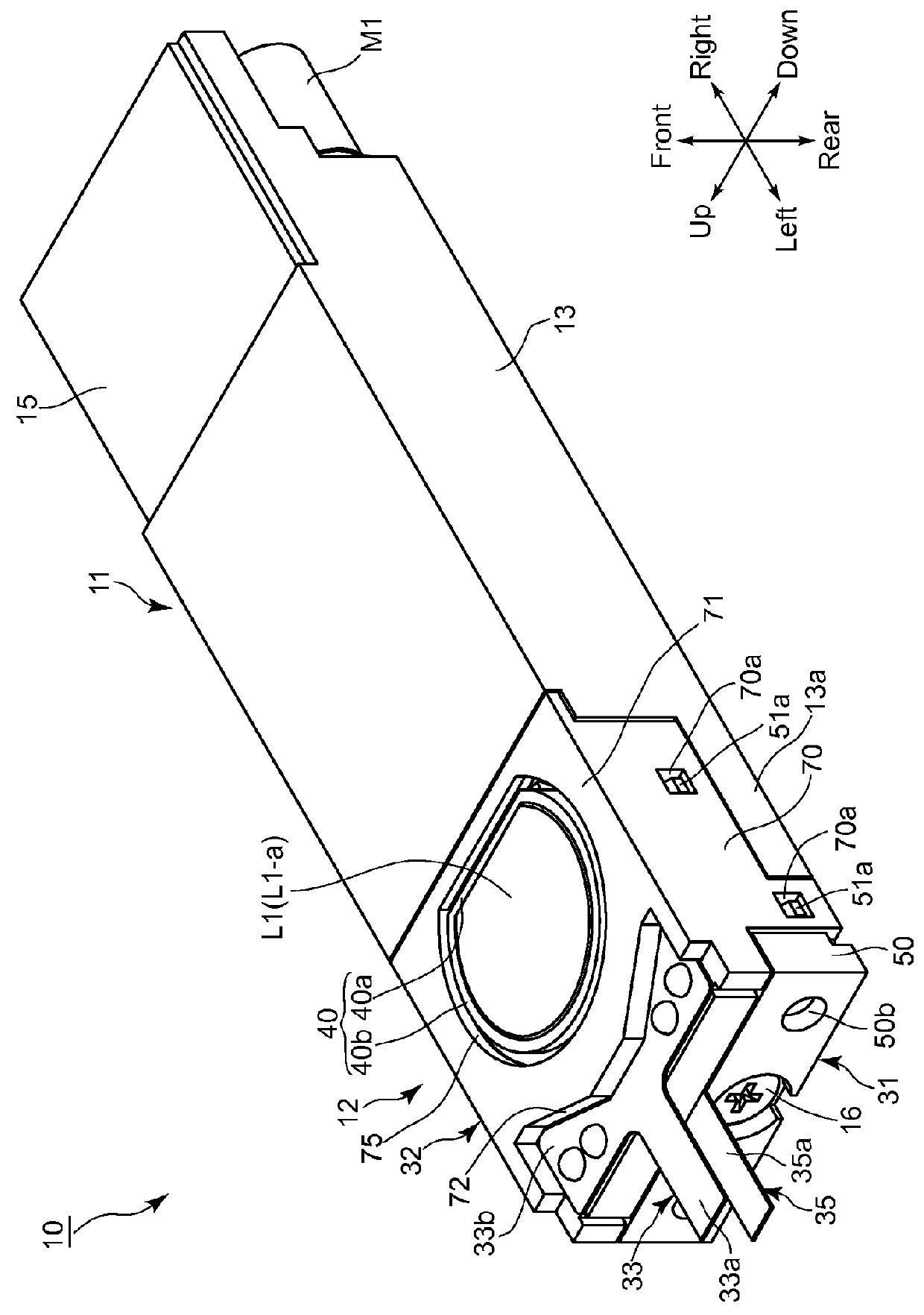
[0056]An embodiment (first embodiment) of an imaging unit (imaging apparatus) 10 according to the present invention will be discussed below with reference to FIGS. 1 through 21. In the following descriptions, forward and rearward directions, leftward and rightward directions, and upward and downward directions are determined with reference to the directions of the double-headed arrows shown in the drawings. The object side corresponds to the front side. As shown by the outward appearance of the imaging unit 10 in FIG. 1, the imaging unit 10 has a laterally elongated shape which is slim in the forward / rearward direction and elongated in the leftward / rightward direction.

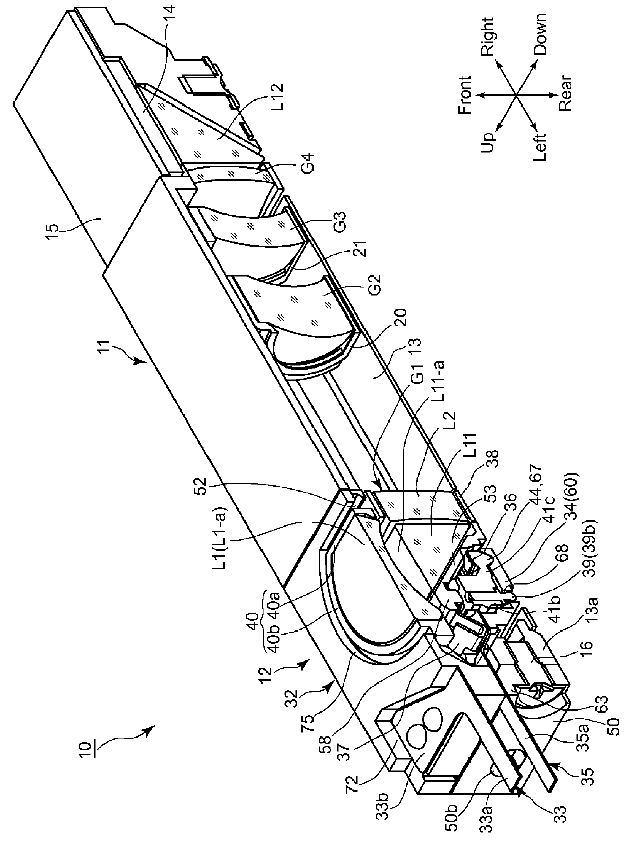
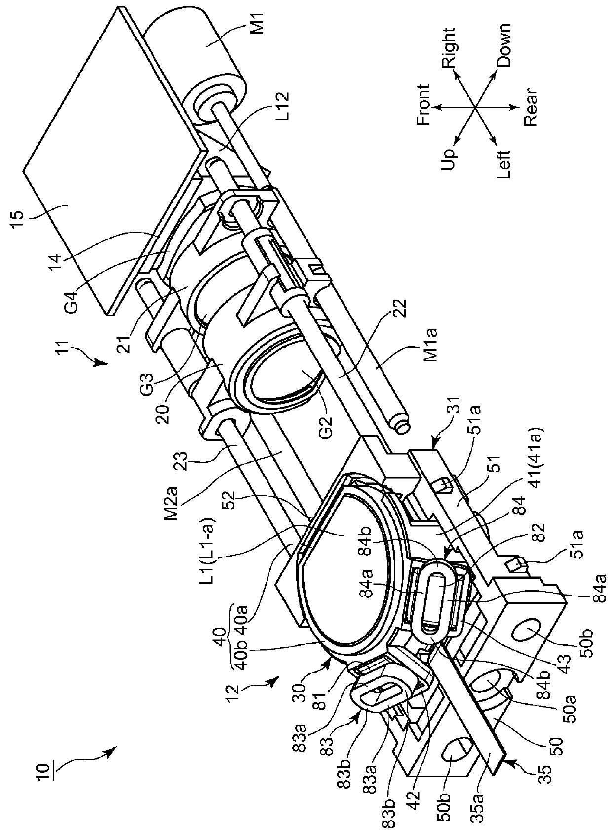
[0057]As shown in FIGS. 2, 4, 6 and 7, an imaging optical system of the imaging unit 10 is provided with a first lens group (front lens group) G1, a second lens group (rear lens group) G2, a third lens group (rear lens group) G3 and a fourth lens group (rear lens group) G4. The first lens group G1 is provided with a fi...

fourth embodiment

[0141]Although the position of one of the two permanent magnets, i.e., the permanent magnet 382, is offset in the imaging unit shown in FIGS. 26 and 27, the other permanent magnet 81 can also be offset in a similar manner to the permanent magnet 382.

[0142]Although one permanent magnet is offset in one direction in the third and fourth embodiments of the imaging units, it is also possible to apply both the offset arrangement shown in the third embodiment of the imaging unit and the offset arrangement shown in the fourth embodiment of the imaging unit to a single permanent magnet.

[0143]Although the offset of the permanent magnet(s) of the actuator has been illustrated in each of the third and fourth embodiments of the imaging units, the presence or absence of an offset arrangement for each of the coil (s) and Hall sensor (s) is optional according to the presence or absence of an offset arrangement of the permanent magnet (s).

[0144]As a first combination, it is possible for straight li...


PUM


Abstract

An imaging apparatus includes a front lens group having a front lens element and a reflector; a support member supporting the reflector; a support mechanism supporting the movable frame, supporting the front lens element, to spherically swing about a center positioned on an extension of the front lens element optical axis behind a reflection surface of the reflector; and a permanent magnet and a coil as an actuator which performs image stabilization by driving the movable frame in response to vibrations to spherically swing the movable frame. The permanent magnet and the coil planarly extend parallel to tangent planes, tangent to imaginary spheres centered about the center, respectively. Any normal to the tangent plane of the permanent magnet is inclined to the optical axis of the front lens element such that a distance between the normal and the optical axis increases in a direction toward the object side.

Description

BACKGROUND OF THE INVENTION[0001]1. Field of the Invention[0002]The present invention relates to an imaging apparatus equipped with an image-stabilizing (image shake correction / shake reduction) system.[0003]2. Description of the Related Art[0004]In recent years, mobile electronic devices which are designed mainly for taking still / moving photographic images, such as digital cameras (still-video cameras) and digital camcorders (motion-video cameras), and other mobile electronic devices which are designed to be capable of taking such photographic images as a subsidiary function, such as mobile phones equipped with a camera and smart devices (smart phones or tablet computers, etc.) equipped with a camera, have become widespread, and there has been a demand to miniaturize the imaging units incorporated in these types of mobile electronic devices. In order to miniaturize an imaging unit, it is known in the art to construct an optical system of an imaging unit as a bending optical system w...

Claims


Application Information

Patent Timeline
Patent Type & Authority Patents(United States)
IPC IPC(8): H04N5/225H04N5/232G02B13/00G02B27/64G03B5/00G03B30/00
CPCG02B27/646G02B13/009G02B13/0045G02B13/0065H04N5/2254H04N5/23248H04N5/23287H04N23/55H04N23/68H04N23/687G03B5/00
Inventor NOMURA, HIROSHISUZUKA, SHINYAMORINAGA, TAKAHIRO
Owner HOYA CORP
Why Eureka
Try Eureka