Pneumatic tire with specified rim strip rubber arrangement

a technology of rim strip and pneumatic tire, which is applied in the field of pneumatic tire, can solve the problems of reducing steering stability, difficult to secure a deteriorating ride comfort, so as to improve the lateral rigidity of the tire, reduce the rigidity of the side portion of the tire, and suppress the rise of vertical rigidity

Inactive Publication Date: 2016-05-17
TOYO TIRE & RUBBER CO LTD
View PDF8 Cites 2 Cited by
  • Summary
  • Abstract
  • Description
  • Claims
  • Application Information

AI Technical Summary

Benefits of technology

[0010]The rim strip rubber provided in the tire extends long in the tire diametrical direction so as to improve a lateral rigidity of the tire by having the thin portion as mentioned above, and all the same time the rise of the vertical rigidity can be suppressed. Further, since the upper end of the thin portion is arranged between the upper end of the bead filler and the roll-up end of the carcass ply, the rigidity of the side portion of the tire is reduced little by little from the buttress area to the bead portion, and the tire side portion smoothly deflects and is deformed one by one toward the inner side in the tire diametrical direction at a time of traveling. As a result, it is possible to achieve the excellent steering stability and ride comfort.
[0011]In the present invention, it is preferable that the rim strip rubber has a coupling portion which stands between the main portion and the thin portion so as to couple the thin portion with the main portion, and is reduced in its thickness little by little from the main portion toward an outer side in the tire diametrical direction. According to the structure mentioned above, a rigidity change between the main portion and the thin portion becomes slow, and it is possible to well improve the ride comfort.
[0012]In the present invention, it is preferable that a thickness of the thin portion is equal to or less than 0.3 times a maximum thickness of the rim strip rubber. Accordingly, it is possible to well improve the ride comfort by appropriately suppressing the rise of the vertical rigidity by the rim strip rubber.
[0013]In the present invention, it is preferable that an upper end of the thin portion is positioned at an intermediate point between the upper end of the bead filler and the roll-up end of the carcass ply or a position closer to the outer side in the tire diametrical direction than the intermediate point. Accordingly, it is possible to well improve the steering stability by appropriately enhancing the lateral rigidity of the tire.
[0014]In the present invention, it is preferable that a length in the tire diametrical direction of the thin portion is between 0.1 and 0.3 times a height in the tire diametrical direction from a reference line extending in the tire width direction through an outer end in the tire diametrical direction of the bead core, to an outermost diameter position of the tire. Accordingly, the thin portion is formed at an appropriate length, and the excellent steering stability and ride comfort can be achieved.

Problems solved by technology

Accordingly, deterioration of a ride comfort tends to be caused.
However, it is hard to secure a lateral rigidity of the tire, by making a thickness of the bead filler smaller, whereby there is a risk that the steering stability is lowered.

Method used


Image

  • Pneumatic tire with specified rim strip rubber arrangement
  • Pneumatic tire with specified rim strip rubber arrangement
  • Pneumatic tire with specified rim strip rubber arrangement

Examples


examples

[0036]In order to specifically indicate the structure and the effect of the present invention, the steering stability and the ride comfort were evaluated, and a description will be given below of the evaluations. Each of the performance evaluations was carried out on the basis of a feeling test (a subjective evaluation) by a driver, by attaching the tire to a sedan type car and executing a straight running travel and a cornering travel. Each of the performances was evaluated by an index number while setting the result of a comparative example 1 to 100, and as the numerical value increases, the performance is much more excellent.

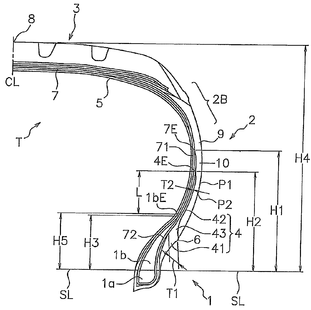
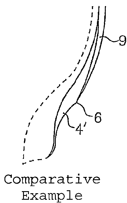
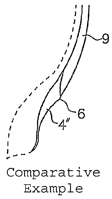
[0037]A size of the tire used for evaluation is 185 / 65R15, and the height H4 from the reference line to the tire outermost diameter position is 112 mm. Except items shown in Table 1, tire structures and rubber compositions in the examples are common. FIG. 2A shows an aspect of FIG. 1 mentioned above. In FIG. 2B, a thickness of a rim strip rubber 4′ is reduced...


PUM


Abstract

A pneumatic tire has a bead filler, a carcass ply, a side wall rubber and a rim strip rubber. The rim strip rubber has a main portion arranged in an outer side in a tire width direction of the bead filler, and a thin portion arranged between the carcass ply and the side wall rubber. The main portion forms an outer surface of a bead portion. The thin portion extends in the tire diametrical direction at a substantially fixed thickness. An upper end of the thin portion is positioned in an outer side in the tire diametrical direction than an upper end of the bead filler and in an inner side in the tire diametrical direction than a roll-up end of the carcass ply.

Description

BACKGROUND OF THE INVENTION[0001]1. Field of the Invention[0002]The present invention relates to a pneumatic tire which can achieve excellent steering stability and ride comfort.[0003]2. Description of the Related Art[0004]Generally, a pneumatic tire has a bead filler constructed by a hard rubber in a bead portion, thereby enhancing a lateral rigidity so as to secure a steering stability. In a pneumatic tire described in Patent Document 1, in order to achieve a weight saving while securing the steering stability, a height of a bead filler is made smaller, and a height of a rim strip rubber which is harder than the bead filler is increased. However, if the height of the hard rim strip rubber is increased, a flexible zone in a side portion of the tire is narrowed and a vertical rigidity is raised. Accordingly, deterioration of a ride comfort tends to be caused.[0005]Further, in a pneumatic tire described in Patent Document 2, an outer portion of a bead filler constructed by a hard rub...

Claims


Application Information

Patent Timeline
Patent Type & Authority Patents(United States)
IPC IPC(8): B60C15/06B60C15/00B60C15/02
CPCB60C15/02B60C15/06B60C2013/007B60C2013/045B60C2015/009B60C2015/061B60C2015/0614Y10T152/10819Y10T152/10828Y10T152/10837
Inventor SHIMA, ICHIRO
Owner TOYO TIRE & RUBBER CO LTD
Why Eureka
Try Eureka