Method for detecting the presence of inhomogeneities in an interior of a turbid medium and device for imaging the interior of turbid media

a technology of inhomogeneity and turbid medium, which is applied in the field of detecting the presence of inhomogeneities in the interior of turbid medium and the use of a device for imaging the interior of turbid media, can solve the problems of optical short circuit, limited detectability and sensitivity of x-ray based equipment, and inability to perfectly match the size of the turbid medium receptacle for receiving the turbid medium. achieve the effect of satisfying

Inactive Publication Date: 2016-05-17
KONINKLIJKE PHILIPS ELECTRONICS NV
View PDF20 Cites 18 Cited by
  • Summary
  • Abstract
  • Description
  • Claims
  • Application Information

AI Technical Summary

Benefits of technology

[0009]It is an object of the present invention to provide a method and a device which allow detecting the presence of inhomogeneities in the interior of a turbid medium with satisfactory accuracy using linear approximation.
[0014]〈M〉=1N⁢∑n⁢Φn⁡(t1)Φn⁡(t2)with N being the number of different combinations of source position and detection position, n being an index for specific combinations of source position and detection position, Φ being the detected photon density, t1 being the time of the first measurement, and t2 being the time of the second measurement. In this case, a normalized merit function with only small deviations from zero can be easily computed based on the averaged term. Thus, linear perturbation theory can be applied and leads to satisfactory results.
[0016]Using a first order Born approximation for reconstructing the image of the interior of the turbid medium is very attractive from a computational point of view, since the required computations can be easily implemented.
[0019]According to an aspect, a contrast agent is injected into the turbid medium before the first measurement is performed. The time interval between the first and second measurements is chosen to be in the order of a decay time of the contrast agent. In this case, the occurrence of non-average wash-out times of the contrast agent can be identified which helps identifying diseased tissue.

Problems solved by technology

Furthermore, X-ray based equipment have a limited detectability and sensitivity.
Due to different sizes of the turbid media to be examined, the size of the receptacle for receiving the turbid medium does not perfectly match the size of the turbid medium, i.e. a space remains between the receptacle and the turbid medium.
An optical short-circuit occurs when light is detected that has propagated along a path inside the receiving volume but outside the turbid medium and, as a consequence, has not been sufficiently scattered and attenuated.
In that case the intensity of the insufficiently scattered and attenuated detected light may dwarf the intensity of detected light that has been scattered and attenuated through passage through the turbid medium.
However, it has been found that the linear approximation is not generally valid between first measurements with only the optically matching medium and second measurements with the turbid medium immersed in the matching medium.
Therefore, the reconstruction achieved using this linear approximation does not always provide satisfactory results.

Method used


Image

  • Method for detecting the presence of inhomogeneities in an interior of a turbid medium and device for imaging the interior of turbid media
  • Method for detecting the presence of inhomogeneities in an interior of a turbid medium and device for imaging the interior of turbid media
  • Method for detecting the presence of inhomogeneities in an interior of a turbid medium and device for imaging the interior of turbid media

Examples


first embodiment

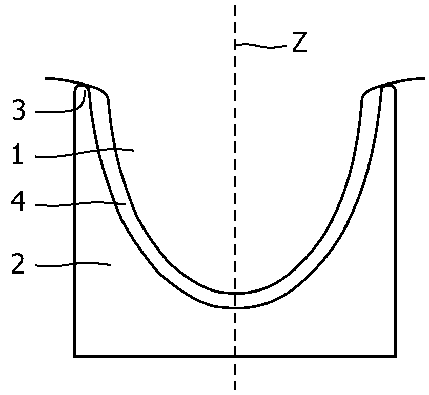
[0042]According to a first embodiment, a fluorescent contrast agent which tends to accumulate in cancer cells is used during examination of the turbid medium 1. For example, the fluorescent contrast agent SF64 by Bayer Schering Pharma is injected into the tissue under examination. The contrast agent accumulates to a higher concentration in lesions than in normal, healthy tissue owing to, among others, a higher degree of vascularization in and around a lesion. Further, in a turbid medium 1 such as a female human breast, the take-up and wash-out of the contrast agent by various structures inside the turbid medium 1 will take place at different time scales. The concentration of the fluorescent contrast agent will decay more slowly at the site of a lesion as compared to normal, healthy tissue. Thus, in the embodiment the fact is used that diseased tissue has a different wash-out time as compared to healthy tissue.

[0043]According to the first embodiment, the turbid medium 1 to which the ...

second embodiment

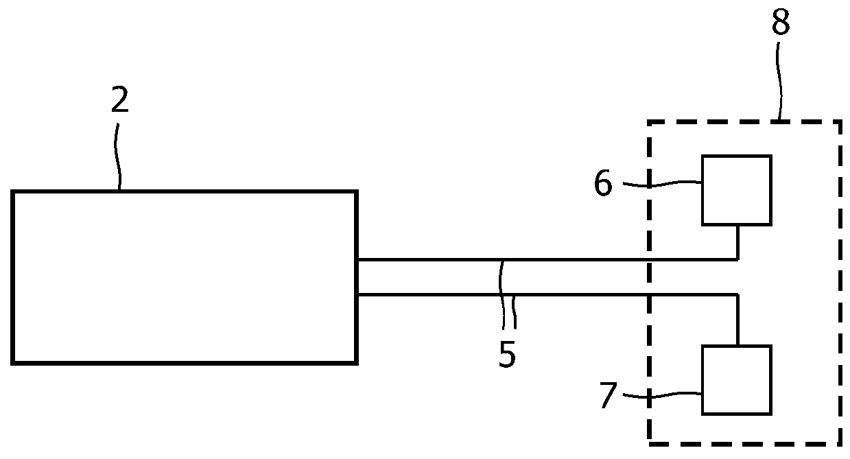
[0049]According to a second embodiment, no fluorescent contrast agent is used. Instead of fluorescence other contrast mechanisms may apply, such as the variation of applied pressure to the turbid medium, the injection of an optically absorbing contrast agent or the difference between the tissue properties during exhaling or inhaling of the breath. At a certain point in time a first measurement for imaging the interior of a turbid medium is performed. For this first measurement, the turbid medium 1 to be examined, e.g. a breast, is placed in the receptacle 2 of the device and a scan in which the light is directed to the turbid medium 1 from different directions is performed. The signals detected by the plurality of detectors 7 are sampled and stored. The results of this measurement, i.e. the set of data generated in this first measurement is then stored for example in a storage in the device for imaging turbid media or in the storage of a personal computer. A second measurement is pe...


PUM

PropertyMeasurementUnit
wavelengthaaaaaaaaaa
volumeaaaaaaaaaa
photon densityaaaaaaaaaa

Abstract

A method includes performing first and second measurements with a turbid medium to be examined placed in a receiving volume of a device for examining the interior of turbid media. The second measurement is performed after a time interval has passed after the first measurement. Each of the first and second measurements includes subsequently irradiating the turbid medium with light from a light source from a plurality of different source positions and detecting light emanating from the turbid medium in a plurality of different detection positions for each source position, and storing the detected values as measurement results. The method also includes detecting inhomogeneities in the interior of the turbid medium by using the measurement results of one of the first and second measurements as a reference and the measurement results of the respective other of the first and second measurements to determine deviations from the reference.

Description

FIELD OF INVENTION[0001]The present invention relates to a method for detecting the presence of inhomogeneities in an interior of a turbid medium and to a device for imaging the interior of turbid media which is adapted accordingly.BACKGROUND OF THE INVENTION[0002]In the context of the present application, the term turbid medium is to be understood to mean a substance consisting of a material having a high light scattering coefficient, such as for example an intralipid solution or biological tissue. Further, light is to be understood to mean electromagnetic radiation of a wavelength in the range from 400 nm to 1400 nm. The term “optical properties” covers the reduced scattering coefficient μ′s and the absorption coefficient μa. Furthermore, “matching optical properties” is to be understood as having a similar reduced scattering coefficient μ′s and a similar absorption coefficient μa.[0003]In recent years, several methods and devices for examining turbid media, e.g. female breast tis...

Claims


Application Information

Patent Timeline
Patent Type & Authority Patents(United States)
IPC IPC(8): A61B5/05G01N21/64A61B5/00G01N21/47
CPCA61B5/0091A61B5/4312G01N21/4795G01N21/6456A61B5/0073
Inventor 'T HOOFT, GERTVAN DER MARK, MARTINUS BERNARDUS
Owner KONINKLIJKE PHILIPS ELECTRONICS NV
Why Eureka
Try Eureka