Compact Cooling Device for an Internal Combustion Engine and Method for Manufacturing Such a Device

a cooling device and internal combustion engine technology, applied in the direction of engine lubrication, mechanical equipment, engine cooling apparatus, etc., can solve the problems of reduced flow rate, reduced efficiency, and reduced efficiency of engine cooling system,

Active Publication Date: 2014-10-16
BONTAZ CENT
View PDF11 Cites 14 Cited by
  • Summary
  • Abstract
  • Description
  • Claims
  • Application Information

AI Technical Summary

Problems solved by technology

In the field of heavy goods vehicles or site plant the engines are subject to particularly high stress and require a more powerful cooling system.
These spray nozzles with two jets comprising two tubes 102, 104 are relatively bulky and, although they can be used in vehicles of the heavy goods or site plant type, they cannot be used in motor vehicles of the “recreational” type or in private

Method used


Image

  • Compact Cooling Device for an Internal Combustion Engine and Method for Manufacturing Such a Device
  • Compact Cooling Device for an Internal Combustion Engine and Method for Manufacturing Such a Device
  • Compact Cooling Device for an Internal Combustion Engine and Method for Manufacturing Such a Device

Examples


Embodiment Construction

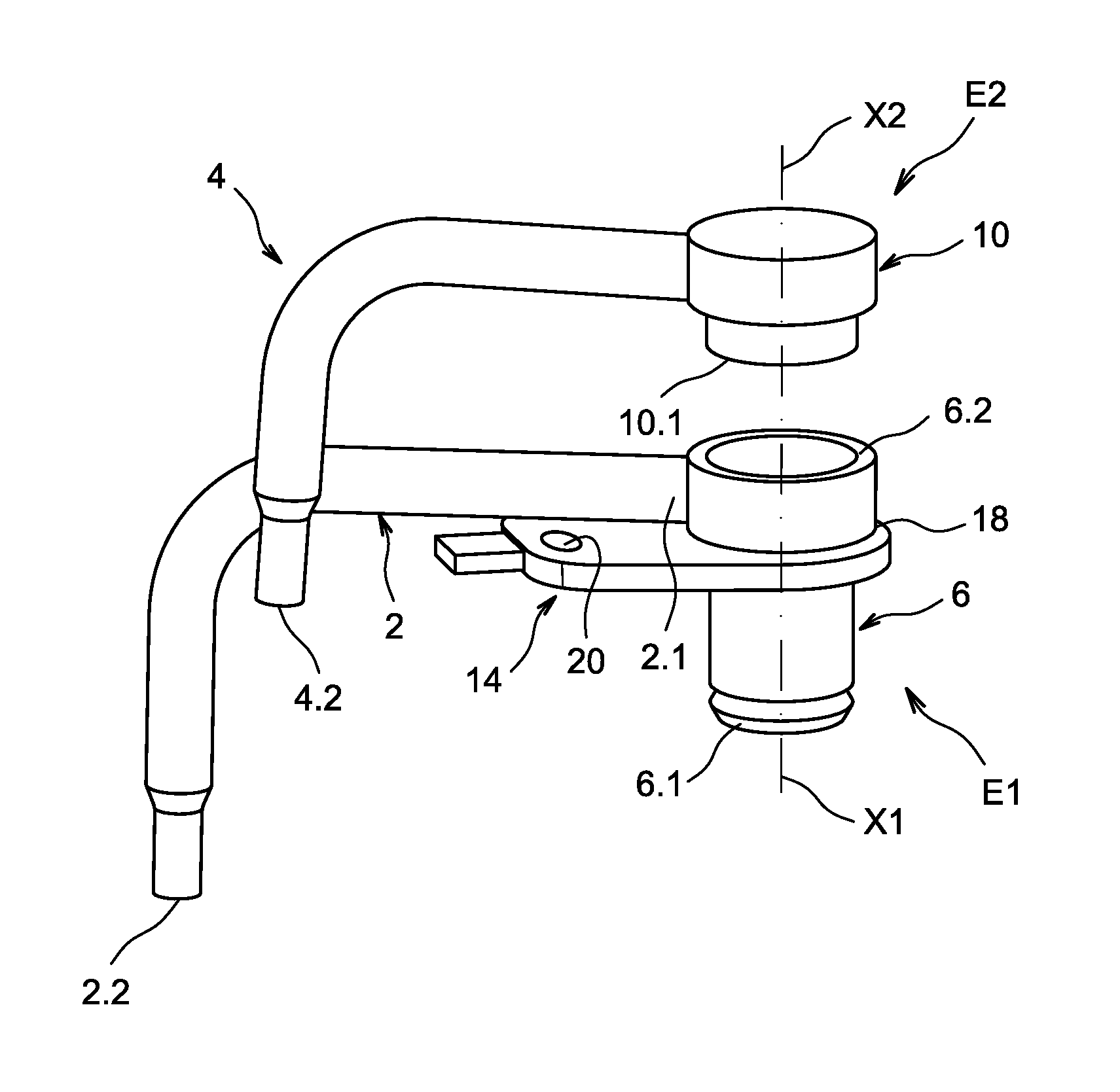
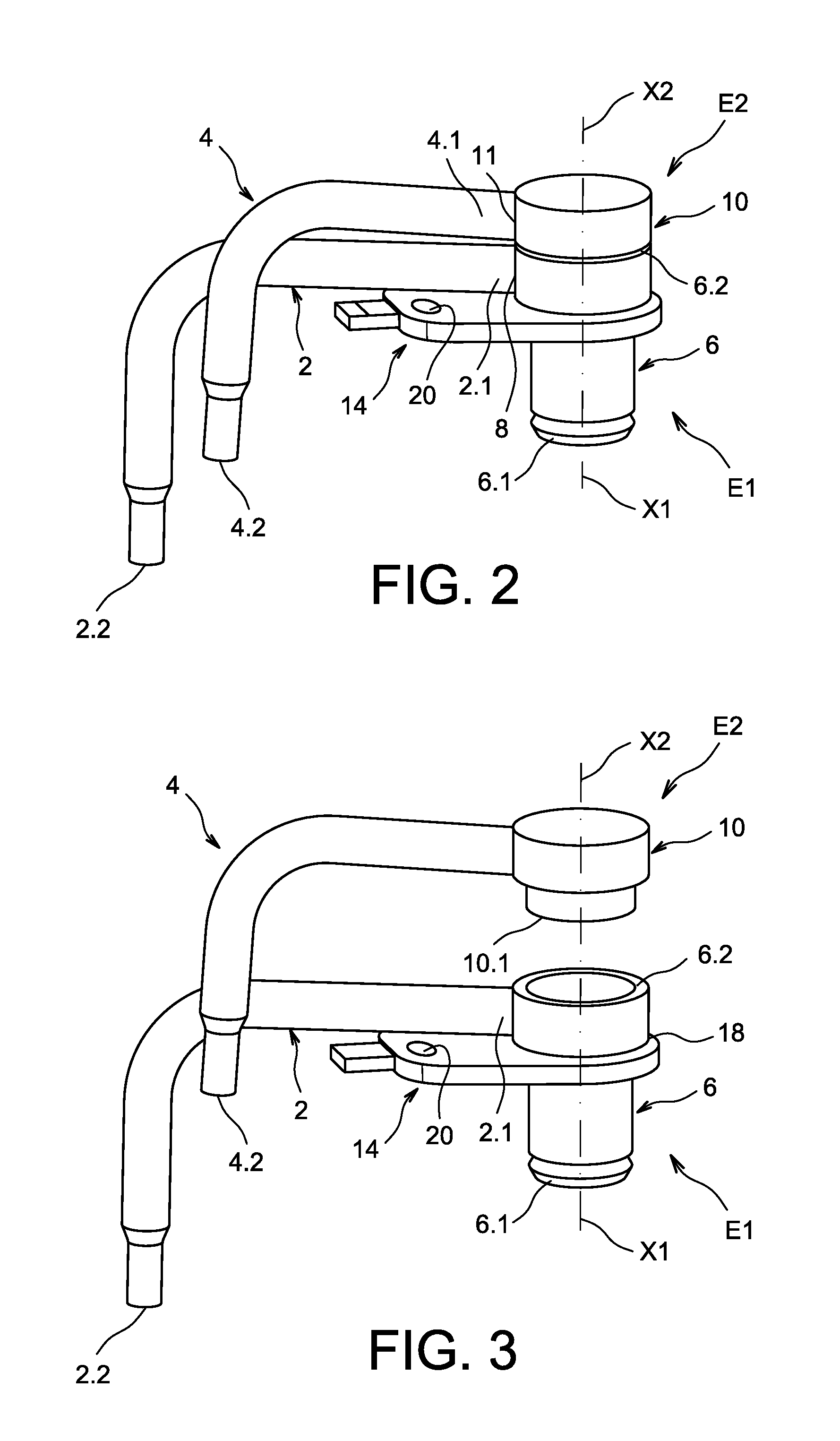
[0009]One aim of the present invention is consequently to provide a cooling device allowing improved cooling, whilst being more compact and having jets with satisfactory target accuracy, and which provides a simplified method of manufacture of such a cooling device.

[0010]The aim mentioned above is attained by a cooling device comprising two superposed separate tubes; by this means the cooling device is made more compact. Each tube also forms with a feed body a subassembly which is manufactured separately from the other subassembly, the tubes being orientated before the two subassemblies are attached to one another. The tubes are then directly correctly orientated, and do not require an orientation step, for example by bending the tubes after assembly. By this means an additional step of bending the tubes is avoided, which would require equipment to be installed between the close tubes, which would pose problems of feasibility.

[0011]The cooling device according to the present inventi...


PUM

PropertyMeasurementUnit
Timeaaaaaaaaaa
Flow rateaaaaaaaaaa

Abstract

A cooling device for a motor vehicle engine connected to a cooling fluid feed system, where said cooling device comprises two superposed subassemblies, where the first subassembly comprises a feed body connected to the feed aperture and a tube connected to the feed body, the free end of which forms a first evacuation end, where the tube extends laterally relative to the feed body and is shaped so as to have a desired orientation, where the second subassembly comprises a feed body connected to the feed aperture and a tube connected to the feed body the free end of which forms the second evacuation end, where the tube extends laterally relative to the feed body and is shaped so as to have a desired orientation, and where the feed bodies are securely attached to one another in sealed fashion.

Description

TECHNICAL FIELD AND PRIOR ART[0001]The present invention relates to a compact cooling device for an internal combustion engine and to a method for manufacturing such a cooling device.[0002]A spray nozzle for cooling a piston of an internal combustion engine enables a cooling fluid such as oil to be projected on to an appropriate area of the piston.[0003]Piston cooling spray nozzles are habitually formed by separate parts attached to the engine block are linked to a cooling fluid inlet aperture. The spray nozzle's position is determined accurately to produce a cooling fluid jet directed towards a precise area of the base of the piston, or towards an inlet of a piston oil channel. In motor vehicles of the recreational vehicle type and private passenger vehicle type the internal combustion engines are fitted with simple spray nozzles, each of which directs a fluid jet on to a piston.[0004]However it is desirable, in order to increase the cooling efficiency, to have several cooling flui...

Claims


Application Information

Patent Timeline
IPC IPC(8): F01P3/06
CPCF01P3/08F01P3/06F01M1/16F01M1/08F01M2001/083Y10T29/49249
Inventor CLEMENT, DENISPEROTTO, STEPHANE
Owner BONTAZ CENT
Why Eureka
Try Eureka