Image processing device, image processing system, image processing method, and program

a technology of image processing and body hair, applied in the field of image processing devices, image processing systems, image processing methods, and programs, can solve the problems of difficult to accurately detect the shape of sulci cutis and cristae cutis if a body hair is present, and the analysis precision becomes lower, so as to achieve the effect of accurately removing body hair in an image, easy and accurate detection, and easy and accurate detection

Active Publication Date: 2016-05-24
SONY CORP
View PDF16 Cites 0 Cited by
  • Summary
  • Abstract
  • Description
  • Claims
  • Application Information

AI Technical Summary

Benefits of technology

[0031]According to the first or second aspect of the present technique, a region showing a detection object such as a body hair in an image can be readily and accurately detected.
[0032]According to the third aspect of the present technique, a region showing a body hair in an image can be readily and accurately detected. Furthermore, according to the third aspect of the present technique, a body hair in an image can be accurately removed.

Problems solved by technology

In a case where a skin condition is analyzed by using an image generated by photographing the skin, it is difficult to accurately detect the shapes of sulci cutis and cristae cutis if a body hair is shown in the image.
As a result, analysis precision becomes lower.

Method used


Image

  • Image processing device, image processing system, image processing method, and program
  • Image processing device, image processing system, image processing method, and program
  • Image processing device, image processing system, image processing method, and program

Examples


first embodiment

[0085]

[0086]Referring first to FIGS. 1 through 12, a first embodiment of the present technique is described.

[0087][Structure Example of Image Processing System 101]

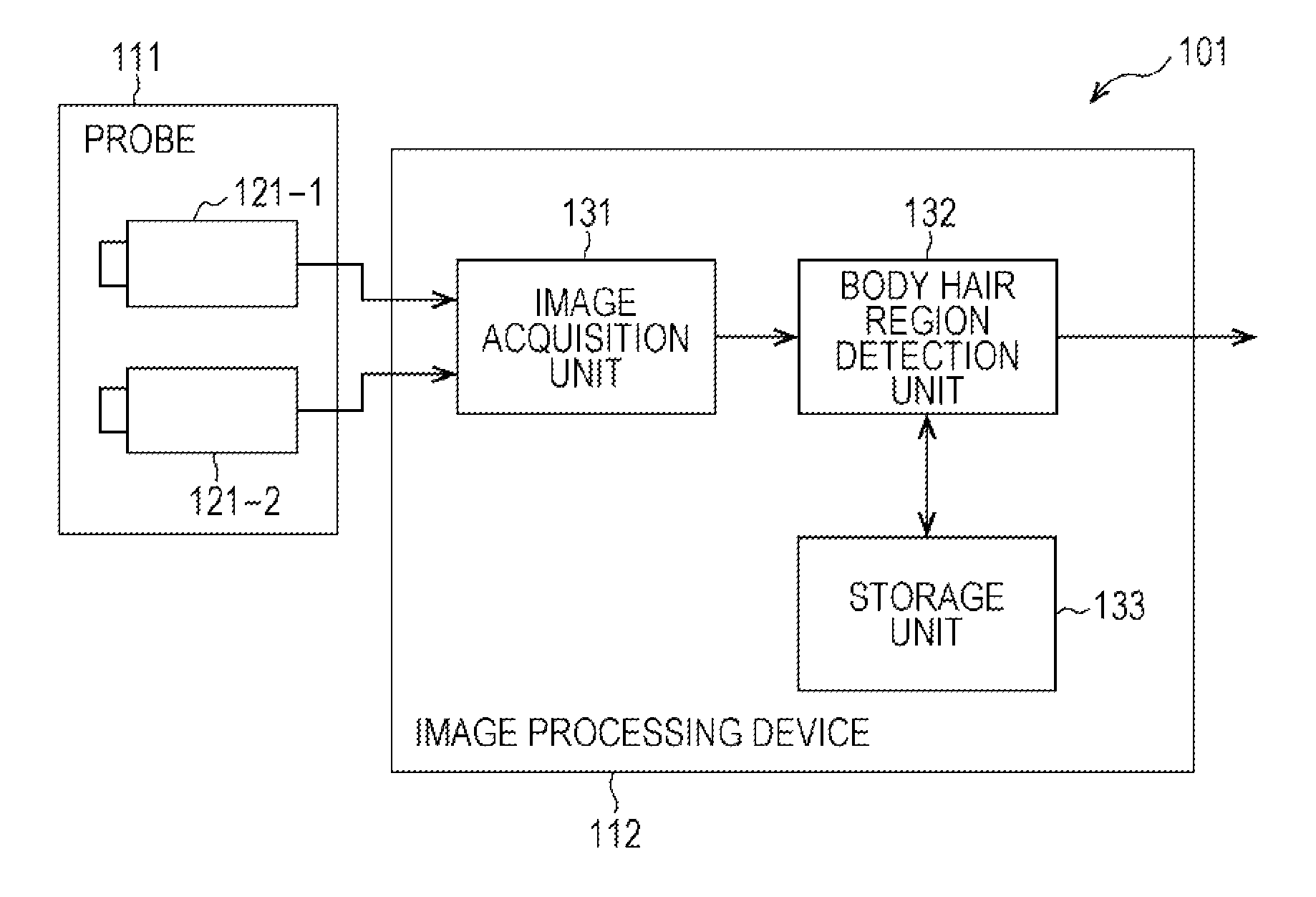
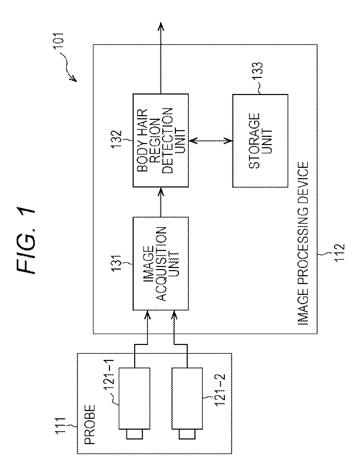
[0088]FIG. 1 is a block diagram showing an example of functional structure of an image processing system 101 as a first embodiment of an image processing system to which the present technique is applied.

[0089]The image processing system 101 is designed to include a probe 111 and an image processing device 112. The image processing system 101 is a system that detects a region that shows a body hair (hereinafter referred to as a body hair region) in an image formed by bringing the probe 111 into contact or close proximity with the skin of a person (hereinafter referred to as a skin image).

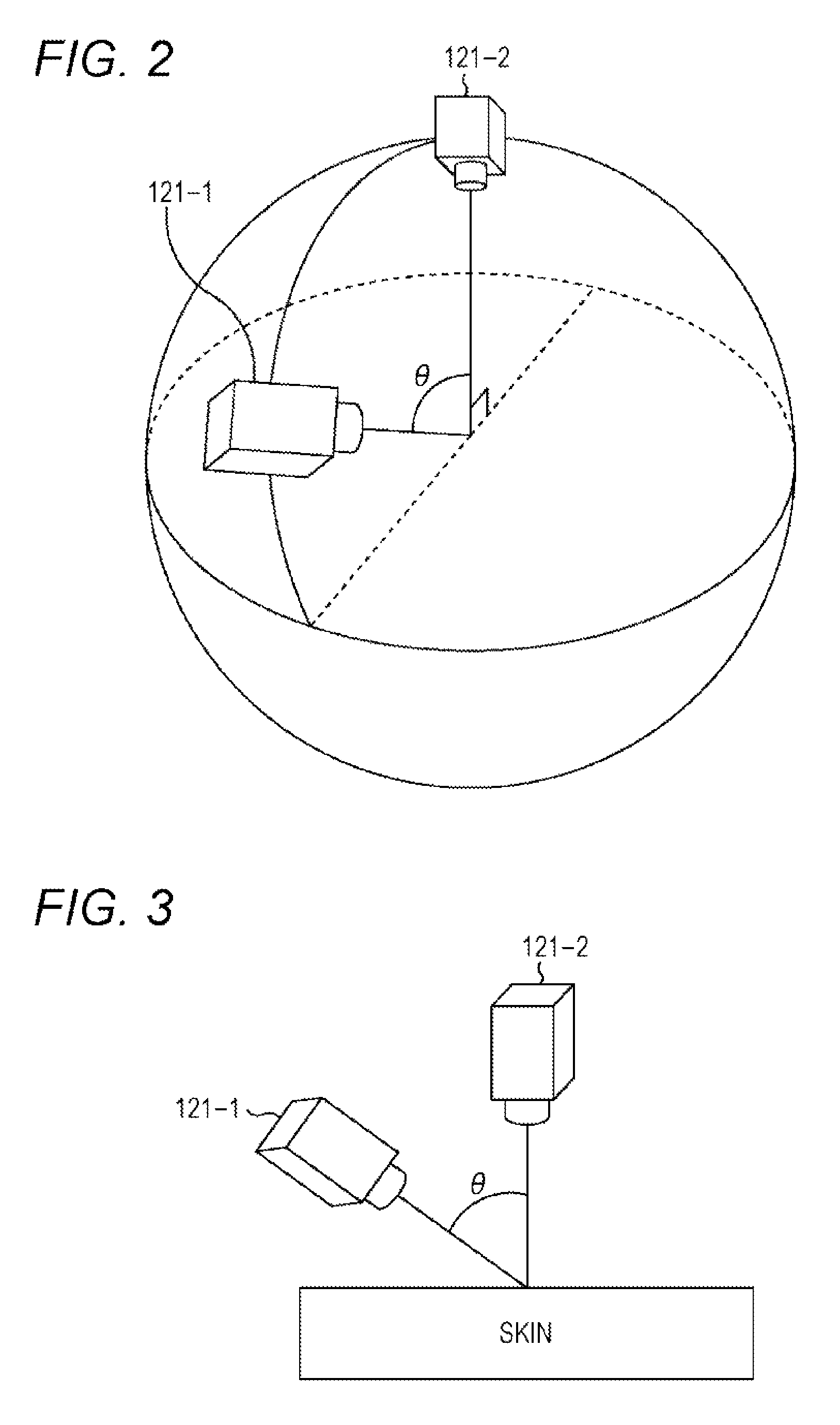
[0090]The probe 111 is designed to include two photographing devices: photographing devices 121-1 and 121-2. The photographing devices 121-1 and 121-2 may be formed with cameras that are capable of taking closeup images from very short dis...

second embodiment

[0149]

[0150]Referring now to FIGS. 13 through 16, a second embodiment of the present technique is described. The second embodiment of the present technique is the same as the first embodiment, except for further including a function to remove a body hair from skin images.

[0151][Structure Example of Image Processing System 201]

[0152]FIG. 13 is a block diagram showing an example of functional structure of an image processing system 201 as the second embodiment of an image processing system to which the present technique is applied.

[0153]The image processing system 201 is a system formed by adding a function of removing a body hair from skin images to the image processing system 101. In the drawing, the components equivalent to those in FIG. 1 are denoted by the same reference numerals as those used in FIG. 1, and explanation of the components that perform the same processes as above is not repeated herein.

[0154]The image processing system 201 differs from the image processing system 1...

third embodiment

[0169]

[0170]Referring now to FIGS. 17 through 23, a third embodiment of the present technique is described. In the third embodiment of the present technique, a body hair region is detected by using three or more skin images acquired by photographing the skin from three or more different directions.

[0171]Since a body hair is in a linear form, it is preferable to capture skin images from two directions that are perpendicular to the extending direction of the body hair, as described above with reference to FIG. 6. This is because doing so will increase the probability (or the area) that a skin region hidden by the body hair in one skin image is not hidden by the body hair but is shown in the other skin image.

[0172]However, a body hair does not always extend in one direction but may extend in various manners. Therefore, skin images are not always captured from two directions perpendicular to the extending direction of a body hair. For example, as shown in FIG. 17, there are cases where ...


PUM


Abstract

The present technique relates to an image processing device, an image processing system, an image processing method, and a program that enable simple and accurate detection of regions showing a detection object such as a body hair in images.A body hair region detection unit includes: a projective transform unit that generates a projected image by projectively transforming a first image generated by photographing a body hair into the coordinate system of a second image generated by photographing the body hair from a different direction from the first image; a difference image generation unit that generates a difference image between the second image and the projected image; and a region detection unit that detects a candidate region formed with pixels having difference values equal to or larger than a predetermined threshold value in the difference image, and divides the region corresponding to the candidate region in the second image into a body hair region showing the body hair and a non-body-hair region outside the body hair region. The present technique can be applied to devices that analyze skin conditions, for example.

Description

CROSS-REFERENCE TO RELATED APPLICATION[0001]The present application is a national phase entry under 35 U.S.C. §371 of International Application No. PCT / JP2012 / 082374 filed Dec. 13, 2012, published on Jul. 4, 2013 as WO 2013 / 099628 A1, which claims priority from Japanese Patent Application No. JP 2011-285560, filed in the Japanese Patent Office on Dec. 27, 2011.TECHNICAL FIELD[0002]The present technique relates to image processing devices, image processing systems, image processing methods, and programs, and more particularly, to an image processing device, an image processing system, an image processing method, and a program that can be suitably used in cases where a predetermined object in images is detected.BACKGROUND ART[0003]In a case where a skin condition is analyzed by using an image generated by photographing the skin, it is difficult to accurately detect the shapes of sulci cutis and cristae cutis if a body hair is shown in the image. As a result, analysis precision becomes...

Claims


Application Information

Patent Timeline
Patent Type & Authority Patents(United States)
IPC IPC(8): G06K9/00G06T5/00G06T7/00G06K9/46A61B5/00G06K9/66
CPCA61B5/441G06K9/00362G06T5/005G06T7/0081A61B2576/02G06T7/11G16H30/40G06V40/10
Inventor SUZUKI, MASARUGOMI, SHINICHIRO
Owner SONY CORP
Why Eureka
Try Eureka