Precision bone drill and method of use

a bone drill and precision technology, applied in the field of drilling devices and drilling procedures, can solve the problems of patient problems, most orthopedic and/or neurological hand-held drill devices do not provide any means of automatic depth control

Active Publication Date: 2016-05-24
PATH SCI LLC
View PDF26 Cites 8 Cited by
  • Summary
  • Abstract
  • Description
  • Claims
  • Application Information

AI Technical Summary

Benefits of technology

[0011]In certain embodiments, the PathFormer D.C. vertical drive motor is replaced by a stepper motor. When a stepper motor is used, there may be no need for the counterelectrode, as the number of steps controls the depth of the drill bit into the bone. In such cases, long drill bits and drill guides may be employed (e.g., as in arthroscopic surgery) to allow drilling of bone deep inside the body. Depth of drilling is controlled by the number of steps programmed into the drill unit. This allows the user to get as close as possible to the far side of a bone—if that is the desired result, and once the proper depth has been achieved, the drill bit is automatically withdrawn. Depth control in such cases may also be based on changes in the motor current (drag) during the drilling process. As bone is drilled, the motor current will change when marrow is drilled, and then again when bone on the opposite side is being drilled.

Problems solved by technology

The screws inserted have to fit properly, such that no unused space remains, which could otherwise cause problems for the patient.
Conventional techniques used for measuring the length of such holes is often done by using a mechanical slide gauge, which is time consuming, and often requires the use of repeated x-ray-control and corrections.
Most orthopedic and / or neurological hand-held drill devices do not provide any means for automatic depth control.

Method used


Image

  • Precision bone drill and method of use
  • Precision bone drill and method of use
  • Precision bone drill and method of use

Examples


example

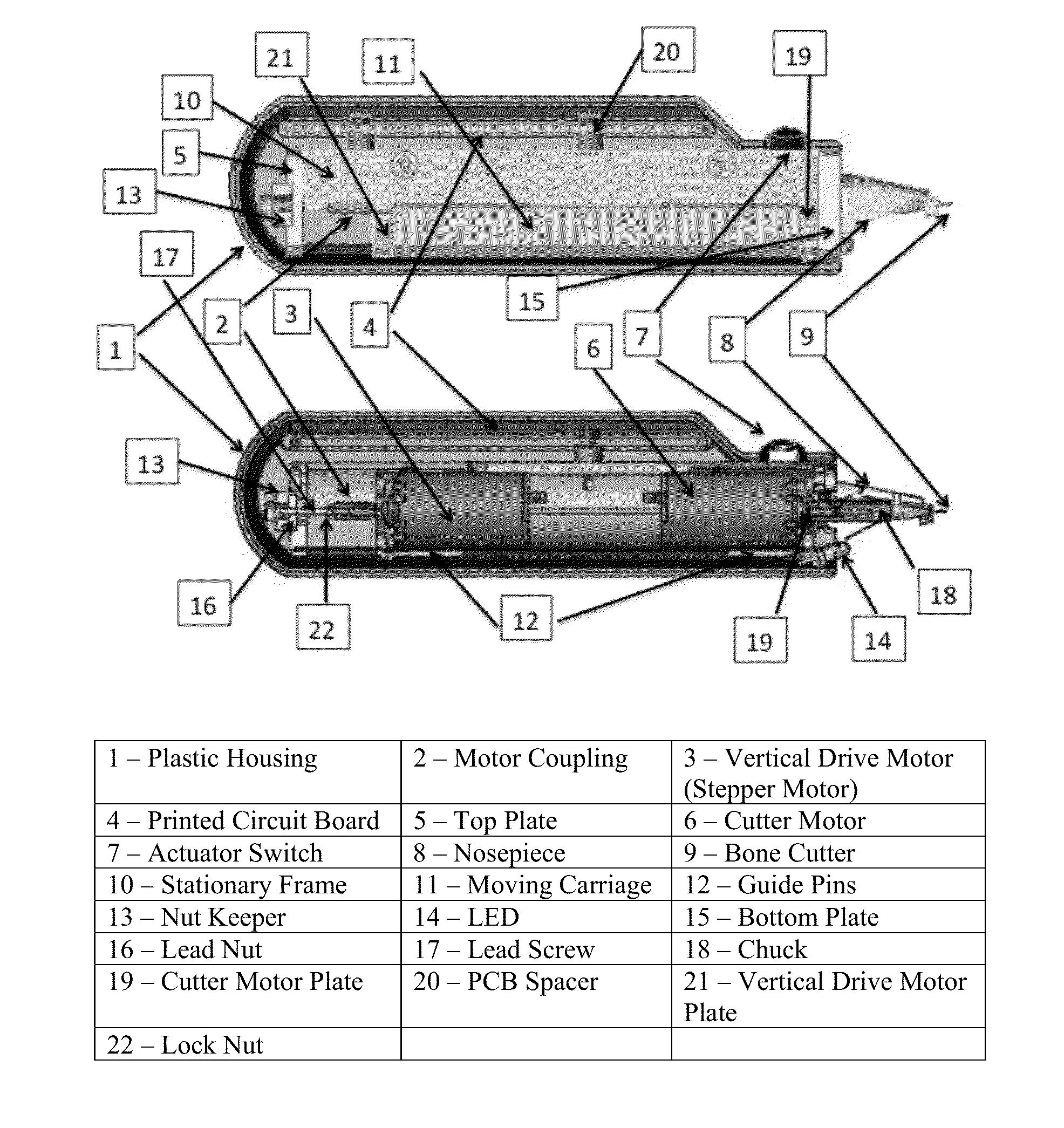
[0085]A cross-section of the bone drill and its components are shown in FIG. 3. The different parts are numbered in the caption. The bone drill consists of the following main functional elements: a bone cutter, foot, a bone cutter drive motor and a vertical drive motor. The cutter drive motor, mounted on a movable chassis, rotates the bone cutter. The vertical drive motor coupled to a lead screw steps the movable chassis toward / into or away / out of the bone tissue.

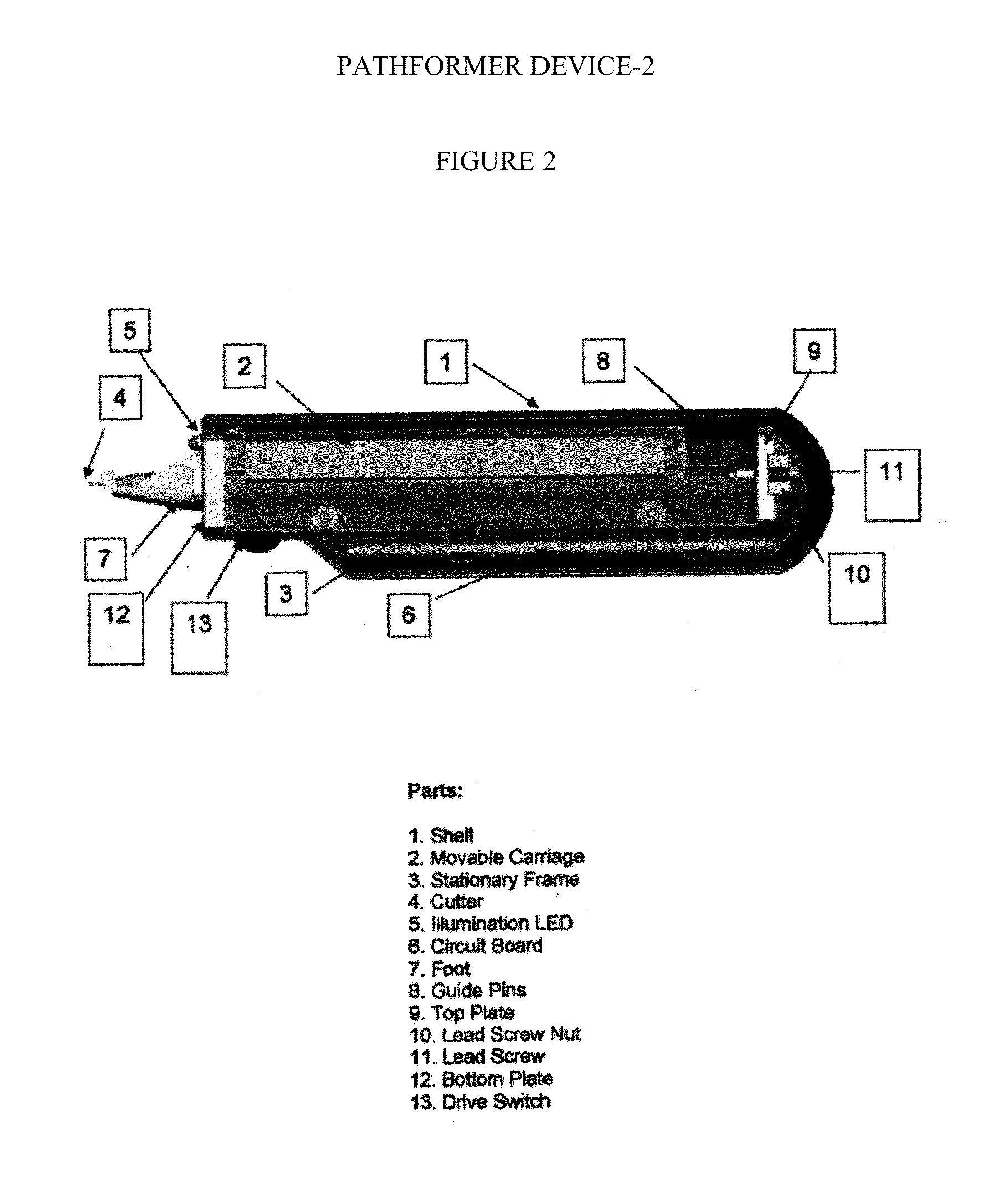
[0086]The components of the bone drill are housed in a plastic outer housing (Parts 1 and 2 in FIG. 3) that is split into fully conforming halves. The hand-actuated switch to operate the drill protrudes through an opening in the housing. The cables to the sensing electrodes are connected to the circuit board. The cables to the power supply are connected through an access port toward the back of the housing (FIG. 4).

[0087]The bone drill chassis has two parts: a stationary frame (Part 10 in FIG. 3) and a movable carriage (par...


PUM


Abstract

Disclosed is a drilling device and a method for the drilling of human or animal bone tissue. The method comprises the following steps; (a) providing a drill having an electrically conductive bone cutter and an electrically conducting nosepiece assembly spaced apart from the electrically conductive bone cutter and acting as a counter electrode; (b) placing the electrically conductive bone cutter and nosepiece assembly into contact with the bone tissue to be drilled; (c) measuring the electrical impedance between the bone cutter tip and the nosepiece or the current through the cutter motor; (d) commencing drilling and moving the bone cutter toward the bone surface; (e) starting a step counter when the impedance reduces or the cutter motor current increases; (f) incrementing the step counter with every step of the vertical drive motor until the step count reaches the prespecified value thereby controlling the depth of the hole drilled.

Description

CROSS-REFERENCE TO RELATED APPLICATIONS[0001]This application is a continuation-in-part of commonly owned copending U.S. patent application Ser. No. 14 / 096,075, filed Dec. 4, 2013, the disclosure of which is hereby incorporated herein by reference. This application also claims benefit of U.S. Provisional Patent Application Ser. No. 61 / 760,856 filed Feb. 5, 2013, the disclosure of which is hereby incorporated herein by reference.FIELD OF THE INVENTION[0002]This invention is directed to a drilling device and a drilling procedure for drilling holes in live human or animal bones. The device is equipped with a rotating drilling drive that includes an automatic stop and withdraw mechanism to ensure precision of depth of drilling.BACKGROUND OF THE INVENTION[0003]Orthopedic and neurological surgeries involve drilling bone to accurate depths. For example, it is often desired that the drill bit does not contact and / or damage the soft tissues and nerves beyond the far cortex of the bone. See, ...

Claims


Application Information

Patent Timeline
Patent Type & Authority Patents(United States)
IPC IPC(8): A61B17/00A61B17/16A61B5/053A61B17/20A61B18/00
CPCA61B17/16A61B5/053A61B17/1622A61B17/1626A61B17/205A61B2017/00026A61B2017/00747A61B2018/00875A61B2090/036A61B2090/062
Inventor HERNDON, TERRYGOWRISHANKAR, THIRUVALLUR R.
Owner PATH SCI LLC
Why Eureka
Try Eureka