Wearable cardiac defibrillator system controlling conductive fluid deployment

a cardiac defibrillator and wearable technology, applied in the direction of heart defibrillators, external electrodes, therapy, etc., can solve the problems of reducing patient discomfort and reducing impedance at the patient location, so as to minimize patient discomfort from irritation or electric shock

Active Publication Date: 2016-05-24
WEST AFFUM HLDG DAC
View PDF9 Cites 26 Cited by
  • Summary
  • Abstract
  • Description
  • Claims
  • Application Information

AI Technical Summary

Benefits of technology

[0009]An advantage over the prior art is that the release of fluid is controlled in certain situations, and patient discomfort from irritation or electric shock can be minimized.

Problems solved by technology

Respective fluid deploying mechanisms can be configured to cause the fluids to be released from one or more of the reservoirs, which decreases the impedance at the patient location, and decreases discomfort for the patient.

Method used


Image

  • Wearable cardiac defibrillator system controlling conductive fluid deployment
  • Wearable cardiac defibrillator system controlling conductive fluid deployment
  • Wearable cardiac defibrillator system controlling conductive fluid deployment

Examples


Embodiment Construction

[0025]As has been mentioned, the present description is about wearable cardiac defibrillators, software, and methods. Embodiments are now described in more detail.

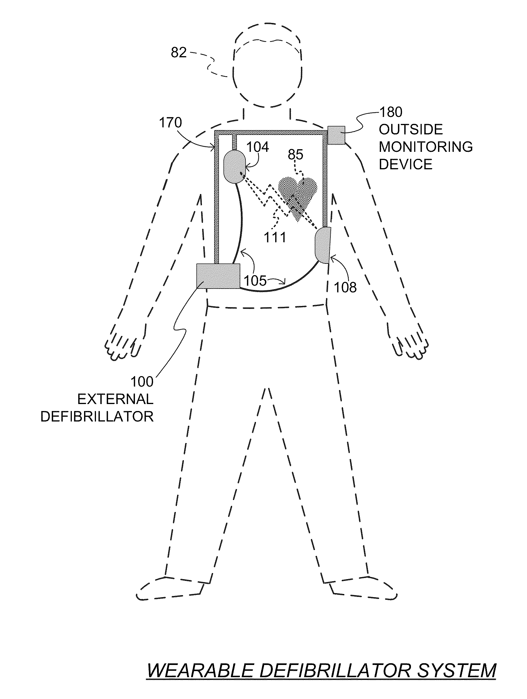
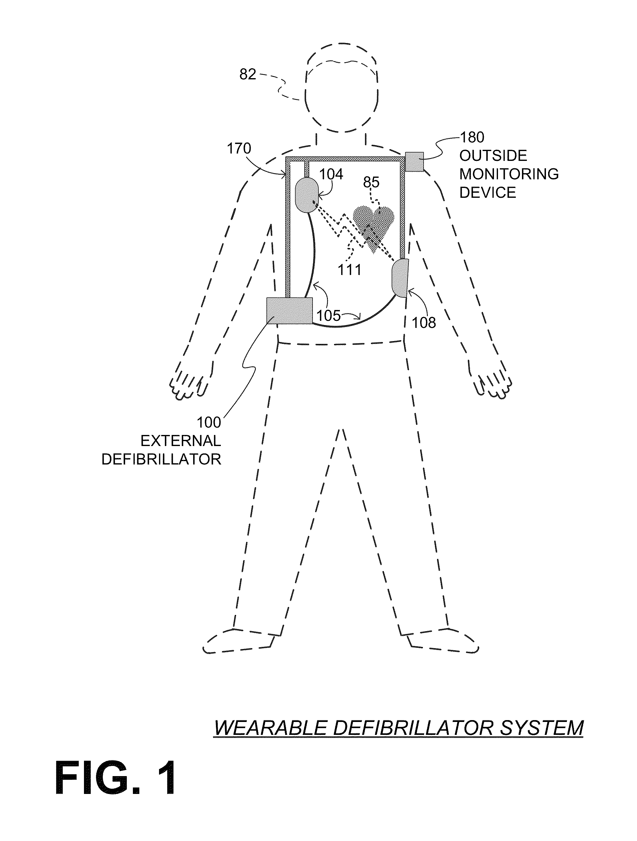
[0026]A wearable defibrillator system made according to embodiments has a number of components. One of these components is a support structure, which is configured to be worn by the patient. The support structure can be any structure suitable for wearing, such as a harness, a vest, one or more belts, another garment, and so on. The support structure can be implemented in a single component, or multiple components. For example, a support structure may have a top component resting on the shoulders, for ensuring that the defibrillation electrodes will be in the right place for defibrillating, and a bottom component resting on the hips, for carrying the bulk of the weight of the defibrillator. A single component embodiment could be with a belt around at least the torso. Other embodiments could use an adhesive structure or anot...


PUM


Abstract

In embodiments, a wearable cardiac defibrillator system includes an energy storage module configured to store a charge. Two electrodes can be configured to be applied to respective locations of a patient. One or more reservoirs can store one or more conductive fluids. Respective fluid deploying mechanisms can be configured to cause the fluids to be released from one or more of the reservoirs, which decreases the impedance at the patient location, and decreases discomfort for the patient. In some embodiments an impedance is sensed between the two electrodes, and the stored charge is delivered when the sensed impedance meets a discharge condition. In some embodiments, different fluids are released for different patient treatments. In some embodiments, fluid release is controlled to be in at least two doses, with an intervening pause.

Description

CROSS REFERENCE TO RELATED PATENT APPLICATIONS[0001]This patent application claims priority from U.S. Provisional Patent Application Ser. No. 61 / 755,919, filed on Jan. 23, 2013, titled: “SYSTEM AND METHOD OF ELECTROLYTE DISTRIBUTION TO AND RETENTION BY ELECTRODES”, the disclosure of which is hereby incorporated by reference for all purposes.[0002]This patent application claims priority from U.S. Provisional Patent Application Ser. No. 61 / 841,222, filed on Jun. 28, 2013, titled: “SYSTEM TO STORE AND DISTRIBUTE ELECTROLYTE TO A DEFIBRILLATION ELECTRODE”, the disclosure of which is hereby incorporated by reference for all purposes.BACKGROUND[0003]When people suffer from some types of heart arrhythmias, the result may be that blood flow to various parts of the body is reduced. Some arrhythmias may even result in a Sudden Cardiac Arrest (“SCA”). SCA can lead to death very quickly, e.g. within 10 minutes, unless treated in the interim.[0004]Some people have an increased risk of SCA. Peopl...

Claims


Application Information

Patent Timeline
Patent Type & Authority Patents(United States)
IPC IPC(8): A61N1/39A61N1/04
CPCA61N1/3918A61N1/0496A61N1/3987A61N1/046A61N1/3625A61N1/3904A61N1/3925
Inventor PIHA, DANIEL RALPHSULLIVAN, JOSEPH LEOFOSHEE, JR., PHILLIP DEWEYFINCH, DANIEL PETERBANVILLE, ISABELLEGUSTAVSON, LAURA MARIECOWAN, KENNETH FREDERICKNOVA, RICHARD C.BUCHANAN, ROBERT REUBENSZUL, KRYSTYNAKAVOUNAS, GREGORY T.
Owner WEST AFFUM HLDG DAC
Why Eureka
Try Eureka