Continuous particle drying apparatus

a drying apparatus and particle technology, applied in drying, light-emitting apparatus, furnace types, etc., can solve the problems of difficult mounting/removing on the apparatus, high cost of belts of such dimensions, and inability to achieve drying methods, etc., to facilitate the transfer of partially dried particles from the upper first deck to the lower second deck, and reduce the generation of dus

Active Publication Date: 2016-05-24
CROSSET LEON
View PDF19 Cites 5 Cited by
  • Summary
  • Abstract
  • Description
  • Claims
  • Application Information

AI Technical Summary

Benefits of technology

[0015]In a first variant of the invention, the first deck is situated below the second deck and the hot gas is preferably hot air circulating from top to bottom, whereas, in a second variant, the first deck is situated above the second deck and the hot gas circulates from bottom to top. The first variant has, among other things, the advantage that the hot gas presses the particles against the surface of the decks which can be advantageous in terms of reducing the dust generated in the case of fine particles. The second variant has the advantage that the transfer of the partially dried particles from the upper first deck to the lower second deck is facilitated by gravity, which can be particularly advantageous for particles of high density.
[0016]Each deck can advantageously comprise a self-supporting rigid structure with high permeability of grating type, on which is placed a filtering layer comprising openings of size and density corresponding to the desired permeability according to the type and size of the particles to be dried. This solution offers great flexibility because it is very easy to replace a perforated plate, a screen, a grid or even a fabric on a grating to successively dry particles of very different granule sizes, which is practically unfeasible with a belt or pallet dryer.
[0019]A third circular deck can be mounted substantially horizontally at a certain distance from, and separated from the first deck by, the second deck, rotating about said vertical axis, Z, in the reverse direction of rotation of the second deck, the surface of said deck being perforated and permeable to the gases such as air and steam and to water. A transfer means makes it possible to transfer the particles collected from the second deck by the second recovery means discussed above to a third distribution means suitable for distributing said particles along a radius of the third deck. This configuration makes it possible to reduce the radius of the disks and therefore the surface area on the ground occupied by the dryer, but it is obviously taller.
[0021]The drying area itself is preferably contained between an outer cylindrical wall of a diameter corresponding to that of the disks, and an inner cylindrical wall, coaxial to the outer wall, and defining a hollow chamber centered on the axis Z of rotation of the decks. The inner wall extends continuously at least from the upper deck to the lower deck. The chamber can advantageously accommodate the fans needed to create the gas flow or the motor driving the rotation of the decks and thus attenuate the noise pollution. It also enables an operator to access different mechanical elements from the interior for the servicing and repairing of the machine.

Problems solved by technology

However, most of the industrial applications require flow rates that a batch drying method cannot achieve.
A belt of such dimensions is very expensive, and difficult to mount / remove on the apparatus.
A belt dryer is therefore generally reserved for the drying of a single type of particles, because it would be uneconomical to change the belt to optimize the type of perforation to a new type of particles.
Should the belt be damaged, the entire unit has to be stopped for a long time, the time it takes to change or repair the belt.
To support a belt over such a length, many support rollers mounted on bearings are necessary, which increases the cost and also the risks of failure of such an apparatus.
A belt dryer is therefore very costly and ineffective in terms of dimension, since the particles are dried only over less than half of the length of the belt.
Although advantageous from this point of view relative to a belt dryer, it is clear that the mechanics necessary for the movements of the decks are delicate and therefore costly and fragile, especially when exposed to fine particles that can seize up the rolling bearings.
Furthermore, the openings created between two adjacent decks and, above all, the spaces opening up in the deck transfer mechanism in each transfer of a deck from the top portion to the bottom portion of the caterpillar track create so many preferential passages of lesser resistance for the flow of hot gas, which result in a significant drop in the efficiency of this type of dryer.
Such a rotary system does indeed have a considerable advantage of space-saving on the ground compared to a linear belt dryer, but such a system lacks efficiency.
In practice, while the hot air having passed through the first decks loaded with very wet particles emerges relatively saturated with moisture, the hot air passing through the final decks loaded with particles already partially dried on the preceding decks emerges with very little moisture content, which represents a considerable waste of energy.

Method used


Image

  • Continuous particle drying apparatus
  • Continuous particle drying apparatus
  • Continuous particle drying apparatus

Examples


Embodiment Construction

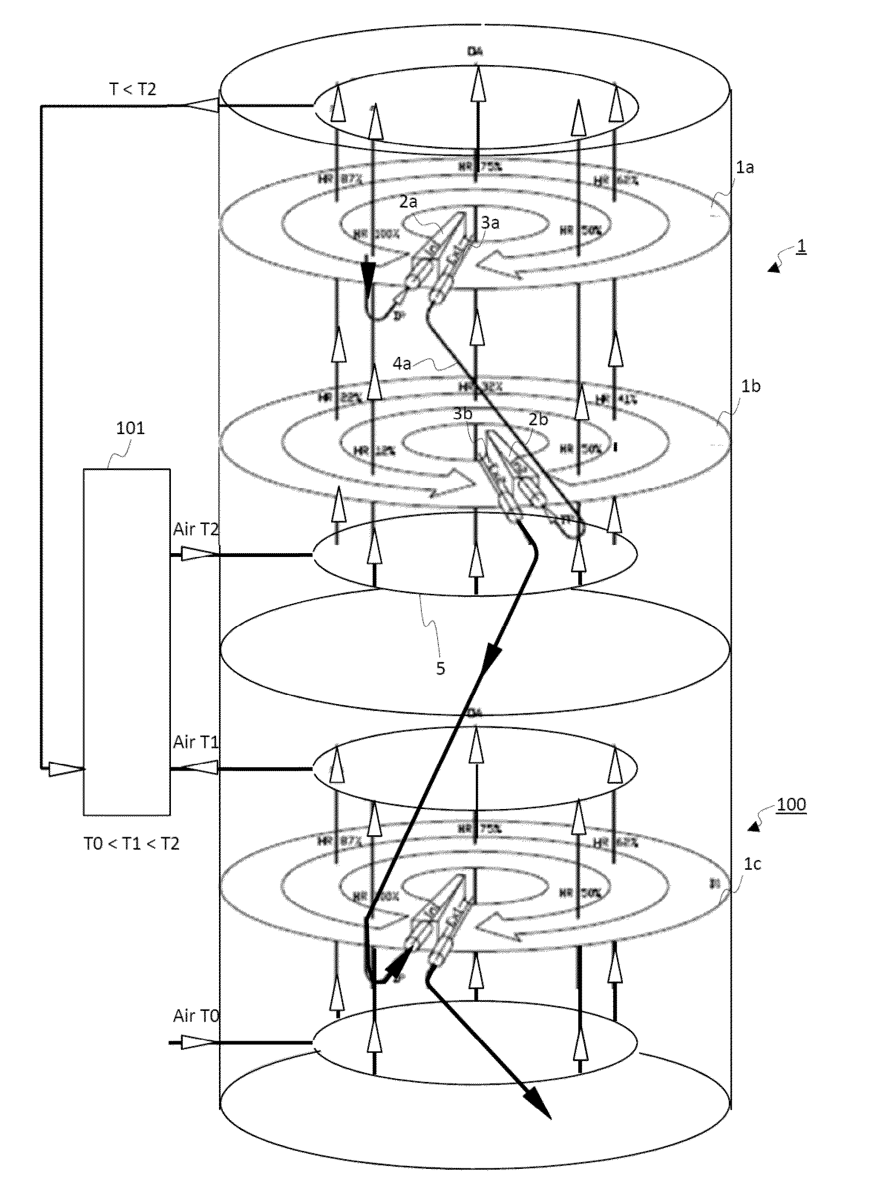
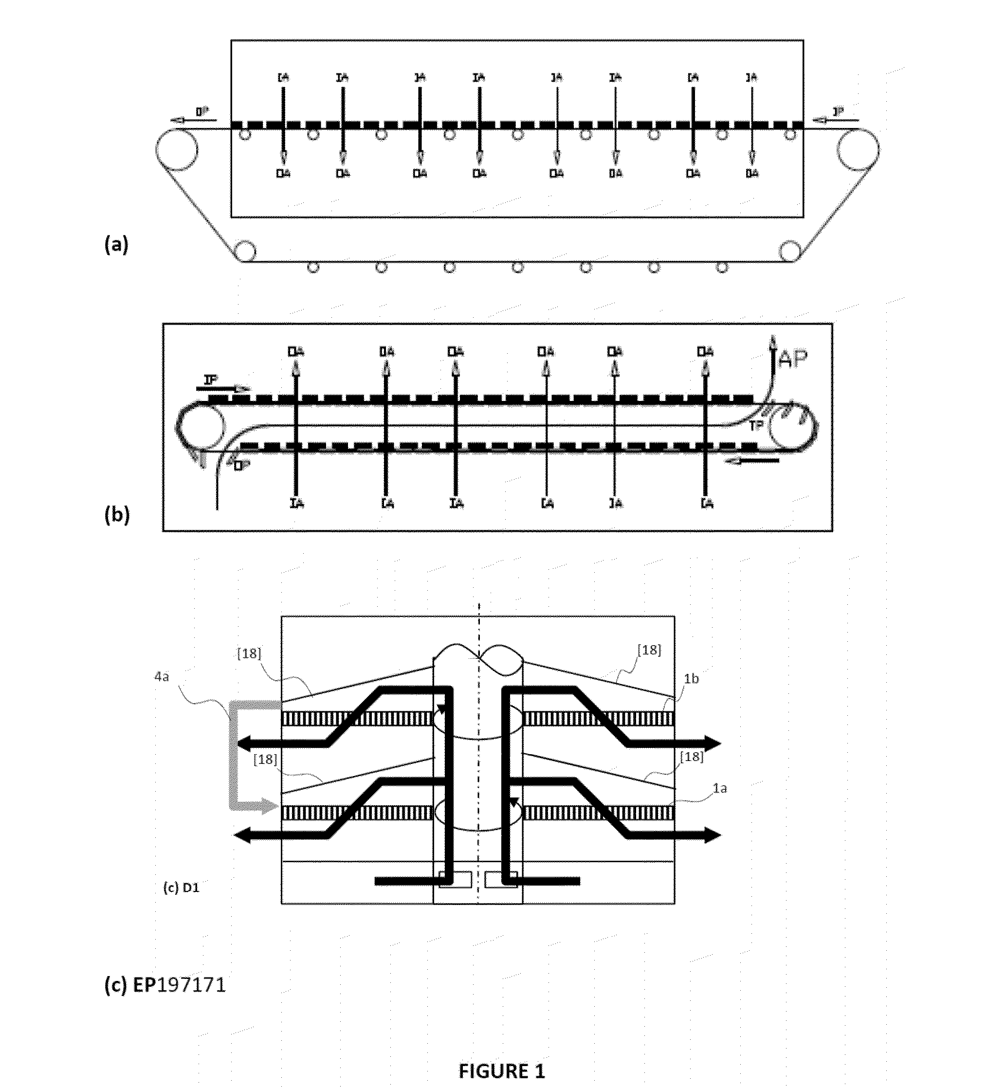
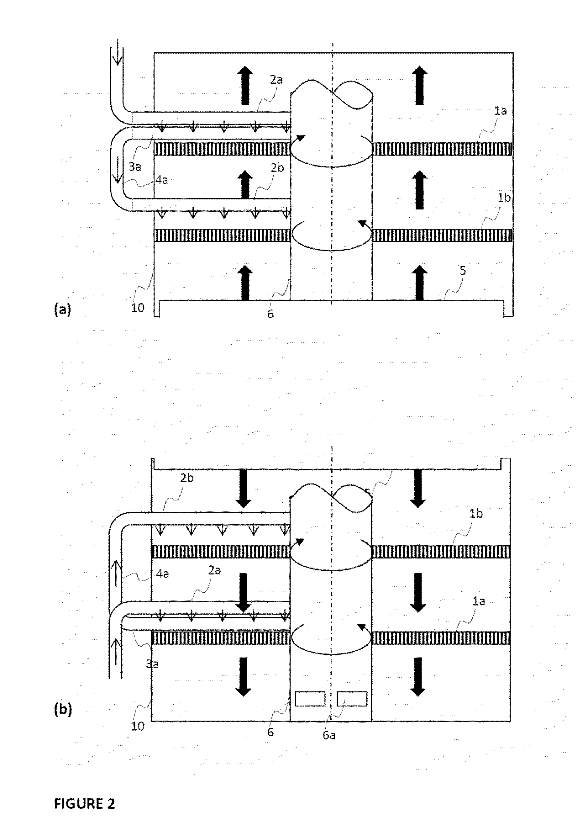
[0033]Unlike the linear motion of the belt or perforated deck dryers currently available on the market for drying particles and represented schematically in FIG. 1, the dryer of the present invention is based on the rotary motions in opposite directions of at least one first and one second superposed deck (1a, 1b). This approach allows for the design of particle drying equipment to be much more compact than the dryers with linear motion. In particular and as illustrated in FIGS. 2 to 4, a dryer according to the present invention comprises a first circular deck (1a) mounted substantially horizontally in rotation in a first direction about a vertical axis, Z, the surface of said deck being perforated and permeable to the gases such as air and steam and to water. A motor (7a) rotates the first deck (1a). A first means (2a) for distributing said particles to be dried is mounted above the first deck so as to be able to distribute said particles before drying along a radius of the first d...


PUM


Abstract

A dryer dries particles, wherein the dryer comprises two circular decks mounted substantially horizontally and rotating in opposite directions relative to one another about a same vertical axis, Z, the surface of said decks being perforated and permeable to air, steam and water, a means for blowing hot gas in a flow substantially parallel to the axis Z, passing through the second deck before passing through the first deck, means for distributing said particles to be dried on the first and second decks and means for recovering the particles after a rotation of each deck, and a means for transferring the particles collected from the first deck by the recovery means to a second distribution means suitable for distributing said particles along a radius of the second deck.

Description

[0001]This application is a 371 application of PCT / EP2013 / 055510 filed Mar. 18, 2013, which claims foreign priority benefit under 35 U.S.C. §119 of Belgium Application No. BE 2012 / 0196 filed Mar. 21, 2012.FIELD OF THE INVENTION[0002]The invention relates to an industrial dryer for drying organic particles, for example of agri-foodstuff origin, such as cereals, or waste used as fuel.TECHNOLOGICAL BACKGROUND[0003]Many industrial methods require particles to be dried before their subsequent use, whether before the packaging of granular agri-foodstuff products or of industrial products, or before the combustion of ground waste used as fuels. It is of course possible to perform the drying of the particles in batches by depositing the particles on decks or in a rotary drum, preferably perforated in order to allow a hot gas to pass through and allow water and steam to escape. In some cases, a fluidized bed is formed by the particles in suspension under the action of the flow of hot gas. Ho...

Claims


Application Information

Patent Timeline
Patent Type & Authority Patents(United States)
IPC IPC(8): F26B21/02F26B23/00F26B25/00F26B3/02F26B17/00
CPCF26B3/02F26B17/005F26B23/001F26B25/003F26B2200/24F26B15/06
Inventor CROSSET, LEON
Owner CROSSET LEON
Why Eureka
Try Eureka