Flip-flops with low clock power

a flip-flop and clock power technology, applied in the direction of pulse generators, pulse techniques, electrical apparatus, etc., can solve the problems of clock power consumption and critical clock power in flip-flops to the overall digital power consumption

Active Publication Date: 2016-05-24
TEXAS INSTR INC
View PDF2 Cites 9 Cited by
  • Summary
  • Abstract
  • Description
  • Claims
  • Application Information

AI Technical Summary

Problems solved by technology

Further, clock power in flip-flops is critical to overall digital power consumption.
The clock power consumption is due to tedious synchronization of the various clock phases and routing of these clock signals within flip-flops.

Method used


Image

  • Flip-flops with low clock power
  • Flip-flops with low clock power
  • Flip-flops with low clock power

Examples


Embodiment Construction

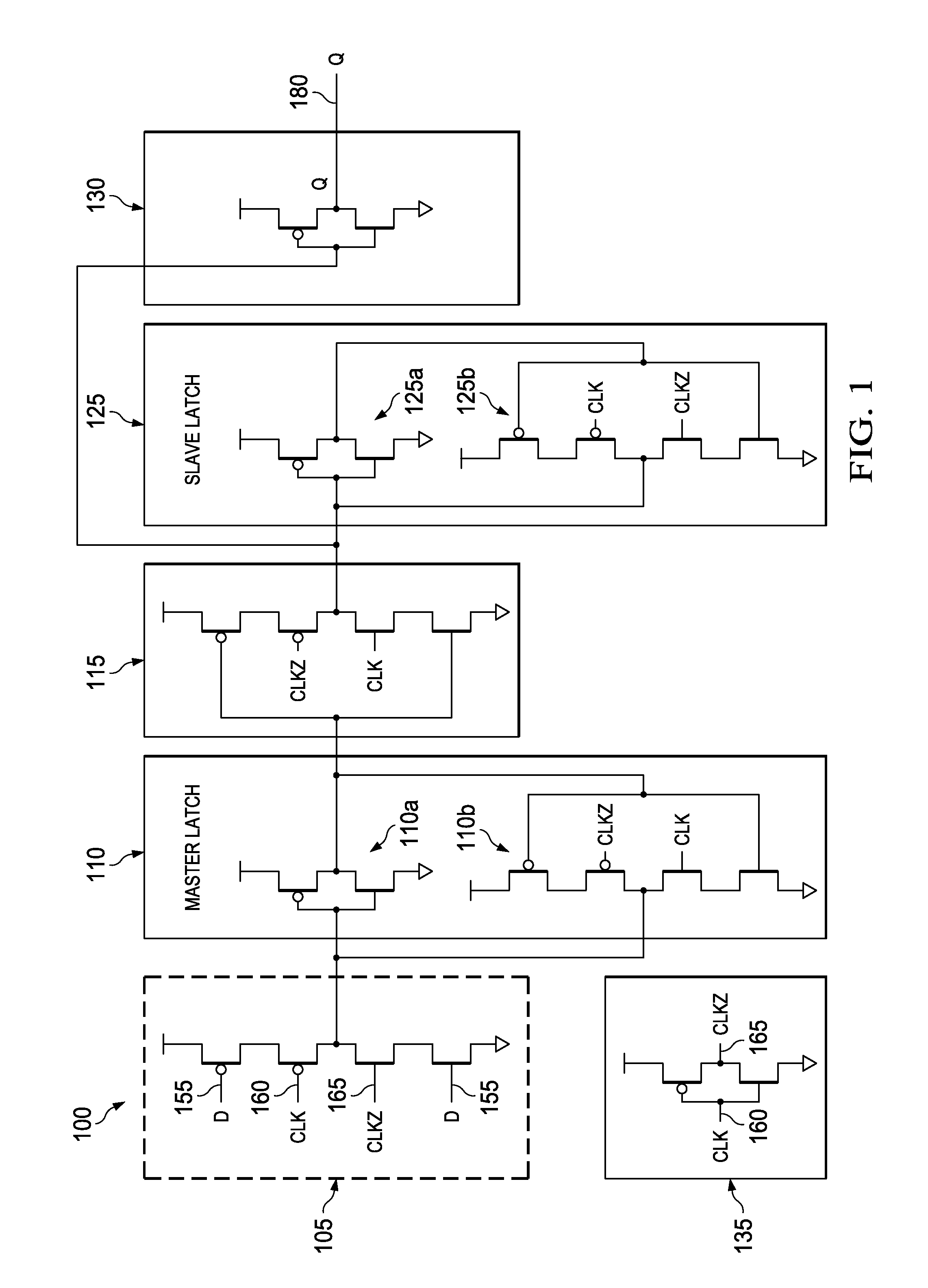
[0014]FIG. 1 illustrates a schematic of a flip-flop 100. The flip-flop 100 receives a flip-flop input D 155, a clock input CLK 160 and an inverted clock input CLKZ 165. A tri-state inverter 105 is coupled to a master latch 110. The output of the master latch 110 is received at a tri-state inverter 115. A slave latch 125 is coupled to the tri-state inverter 115. The master latch 110 and the slave latch 125 are implemented using two back-to-back inverters.

[0015]The back-to-back inverters include an inverter 110a and a tri-state inverter 110b in the master latch 110 and an inverter 125a and a tri-state inverter 125b in the slave latch 125. An output of the slave latch 125 is equal to an output of tri-state inverter 115. The output of the slave latch 125 is received at a data inverter 130. The data inverter 130 generates a flip-flop output Q 180. An inverter 135 receives the clock input CLK 160 to generate the inverted clock input CLKZ 165.

[0016]The operation of the flip-flop illustrate...


PUM


Abstract

The disclosure provides a flip-flop that utilizes low power as a result of reduced transistor count. The flip-flop includes a tri-state inverter that receives a flip-flop input and a clock input. A master latch is coupled to an output of the tri-state inverter and provides a control signal to the tri-state inverter. The control signal activates the tri-state inverter. A slave latch receives an output of the master latch and the control signal. An output inverter is coupled to an output of the slave latch and generates a flip-flop output.

Description

TECHNICAL FIELD[0001]Embodiments of the disclosure relate to flip-flops with low clock power in an integrated circuit.BACKGROUND[0002]As a result of the continuous developments in integrated circuits (ICs), the flip-flops contribute to a substantial portion of any circuit design's power. The various units of an IC that consume power are logic implementation, flip flops, RAM, clock tree and integrated clock gating (ICG) cells. The comparison of the power consumption by the various units is as follows; logic implementation 29%, flip-flops 27%, RAM 18%, clock tree 16% and the ICG consumes 10% of the total power in a typical design. In digital designs, the flip-flops form 20-40% of the digital sub-chips.[0003]The majority of power inside a flip-flop is consumed by the transistors receiving a clock input, since the data activity factors are typically much lower. Irrespective of whether the data changes every cycle or not, the transistors receiving the clock input keep switching at every ...

Claims


Application Information

Patent Timeline
Patent Type & Authority Patents(United States)
IPC IPC(8): H03K3/012H03K3/037
CPCH03K3/012H03K3/0372
Inventor NANDI, SUVAMSUBBANNAVAR, BADARISH MOHAN
Owner TEXAS INSTR INC
Why Eureka
Try Eureka