Isolation dimmer circuit structure

a technology of isolation dimmer and circuit structure, which is applied in the direction of electroluminescent light source, electric lighting source, and use of semiconductor lamps, etc., can solve the problems of increasing cost, prolonging development time course, and traditional dimmer circuits cannot be applied directly to lightings using leds as light sources, so as to reduce product development and production costs and increase the overall economic benefits

Active Publication Date: 2016-05-24
YUJING ENERGY TECH CO LTD
View PDF4 Cites 11 Cited by
  • Summary
  • Abstract
  • Description
  • Claims
  • Application Information

AI Technical Summary

Benefits of technology

[0011]One main objective of the present invention is to provide an isolation dimmer circuit structure for receiving and converting control signals output by various different traditional dimmer circuits in order to control energy-efficient LED light sources, so that various dimmer circuits used for traditional light sources can also be used to control LED light sources, thereby reducing product development and production costs and increasing the overall economic benefits.
[0012]Another objective of the present invention is to provide an isolation dimmer circuit structure that protects the circuit components from reversed voltage polarities and overvoltage to prevent damage caused by production or operational errors.

Problems solved by technology

Since traditional light source elements and LED elements are significantly different in terms of light-emitting principles and electrical characteristics, a traditional dimmer circuit cannot be applied directly on lightings using LEDs as the light source.
1. Since the converting circuits are specially designed according to the control methods (resistive, voltage or PWM type) of the traditional dimmer circuits, so converting circuits for different types of dimmer circuits have to be developed separately and cannot be used interchangeably. This lengthens the development time course and increases the cost, so it is not economical.
2. During the assembly process of the converting circuit and the traditional dimmer circuit, if there is an operational error (e.g. voltage polarities are reversed) or usage error (e.g. voltage is too high), circuit components may be damaged. In order to prevent such damages, a complicated protection mechanism (circuit) is required in the converting circuit. This kind of protection mechanism (circuit) will inevitably increase the overall cost.

Method used


Image

  • Isolation dimmer circuit structure
  • Isolation dimmer circuit structure
  • Isolation dimmer circuit structure

Examples


first embodiment

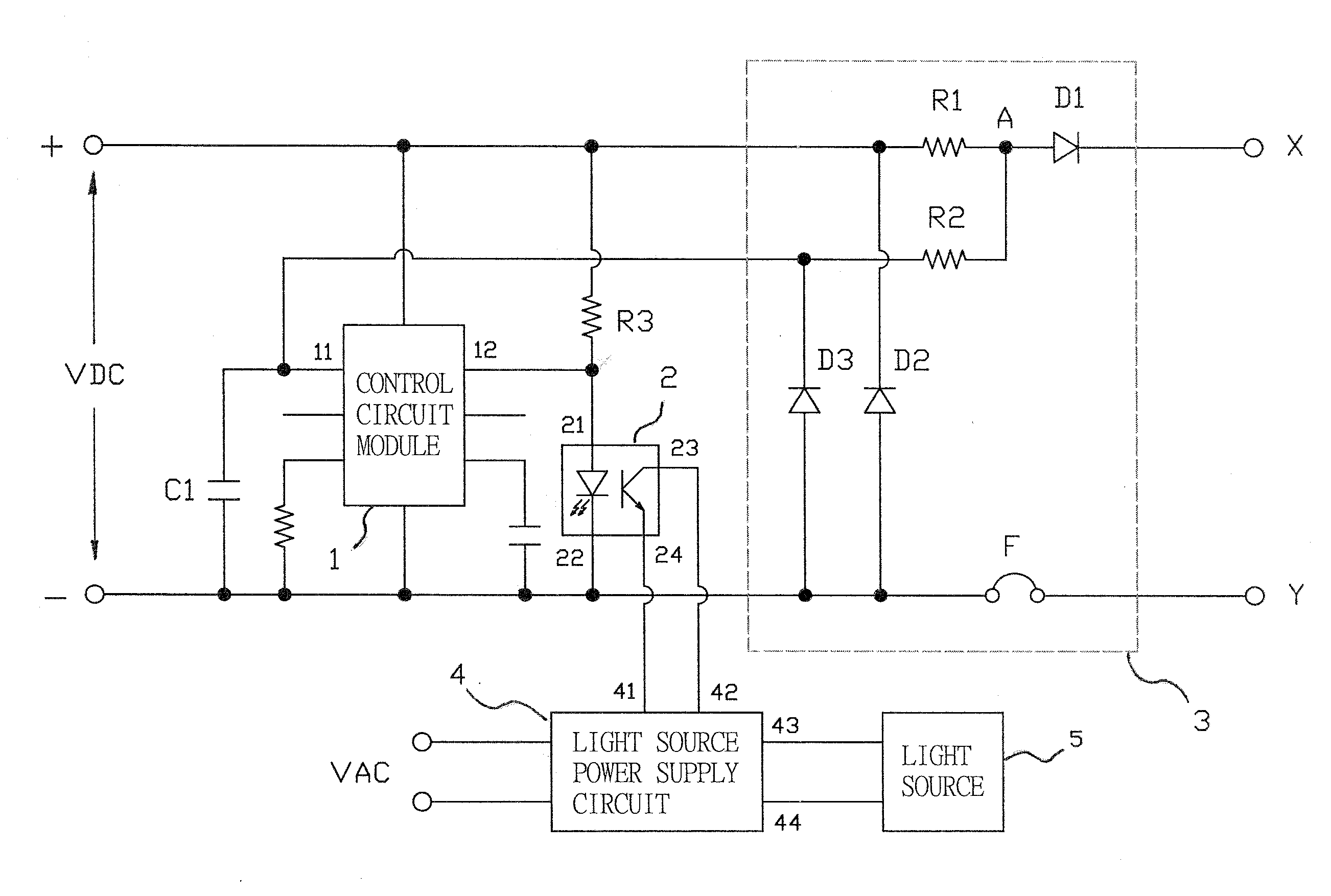
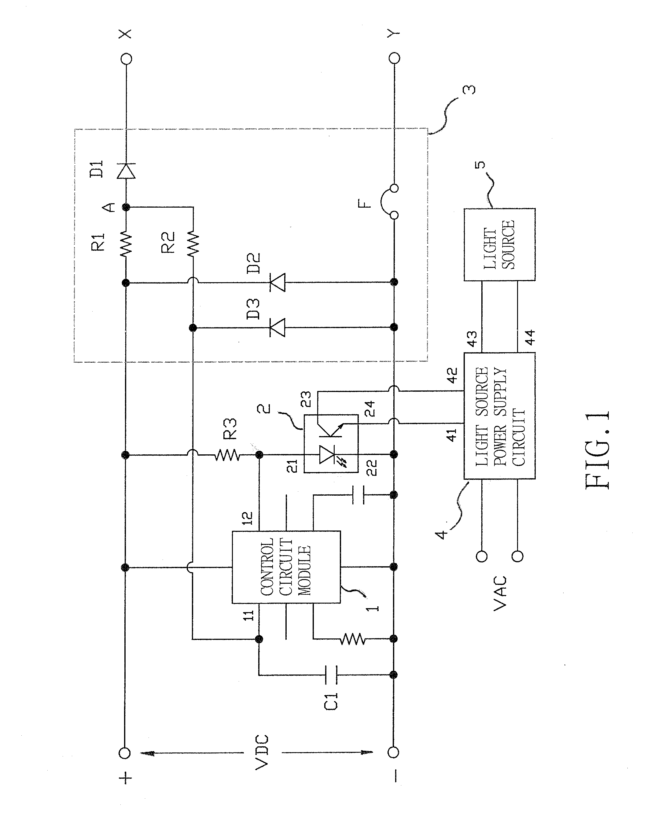
[0027]Referring to FIG. 1, a circuit structure in accordance with the present invention essentially includes: a control circuit module 1, an optocoupler 2 and a protection circuit 3. The control circuit module 1 is provided between the positive and the negative terminals of a DC power supply VDC. The control circuit module 1 has an input end 11 for receiving a sensing signal and an output end 12 for outputting a control signal.

[0028]The optocoupler 2 includes an input end 21 connected to the output end 12 of the control circuit module 1, and another input end 22 connected to the negative terminal of the DC power supply VDC. The optocoupler 2 includes two output ends 23 and 24 connected to input ends 41 and 42 of a light source power supply circuit 4, respectively.

[0029]In one implementation, the light source power supply circuit 4 includes output ends 43 and 44 connected to a light source 5 (which can be a LED). The light source power supply circuit 4 is able to convert an external ...

second embodiment

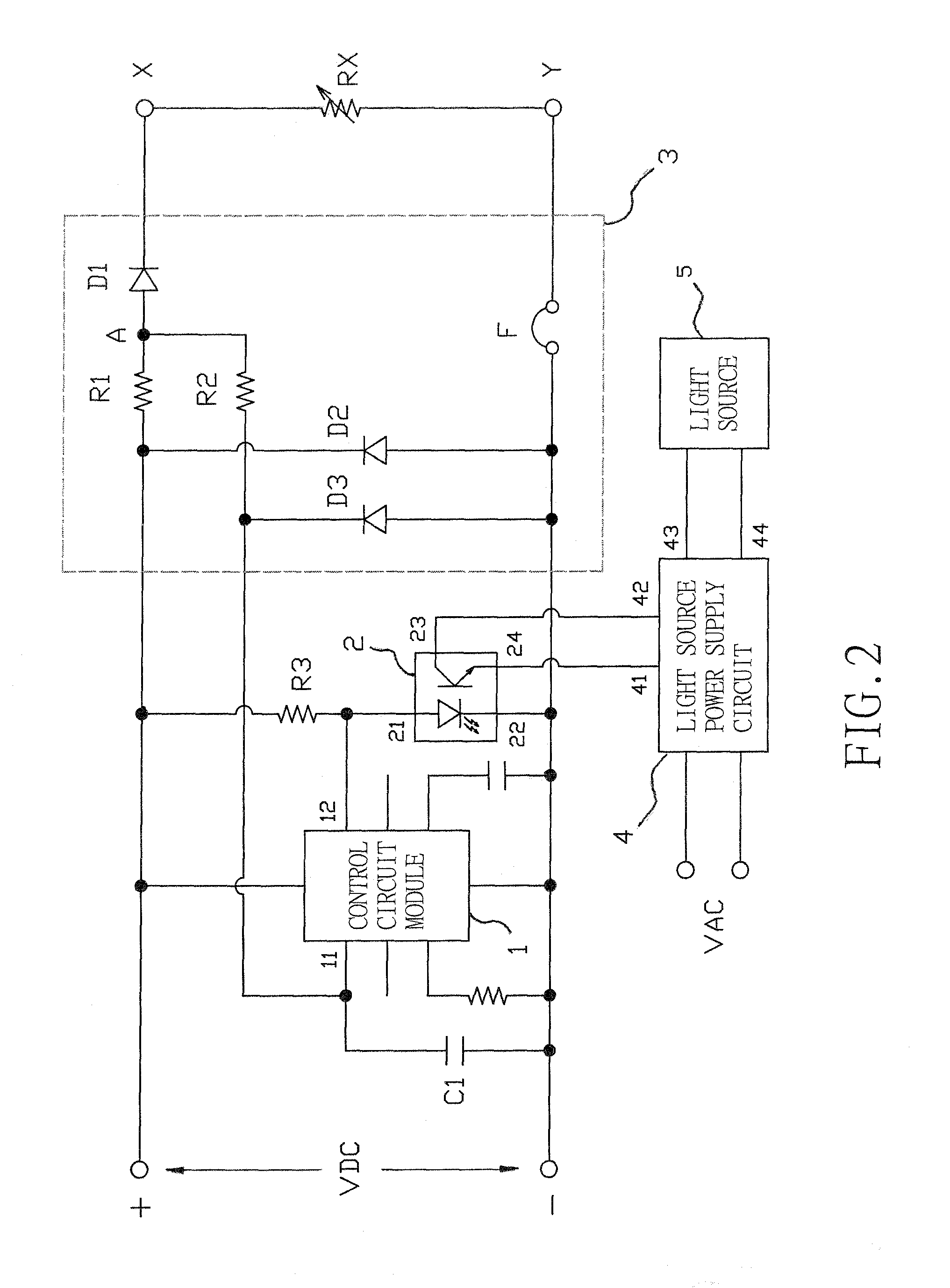
[0048]When the circuit structure in accordance with the present invention is connected with a traditional dimmer mechanism having a variable resistive characteristic, this can be regarded as adding a (variable) resistor RX load between the first and the second terminals X and Y of the control input end. Meanwhile, the control circuit module 1 outputs a current I through the input end 11. The current I passes through the second resistor R2, the first diode D1 and the (variable) resistor RX. A voltage drop VX is created between the two ends of the (variable) resistor RX (VX=I*RX; when the resistance RX changes, the voltage VX changes accordingly), and a voltage VA′ is created at the node A (VA′=VX+0.1˜0.2V).

[0049]The voltage VA′ charges the capacitor C1 via the second resistor R2, thus creating a sensing signal that is input into the control circuit module 1 through the input end 11. The control circuit module 1 outputs a corresponding control signal from the output end 12. The contro...


PUM


Abstract

An isolation dimmer circuit structure includes a control circuit module having an input end for receiving a sensing signal and an output end for outputting a control signal. An optocoupler is provided between the control circuit module and a light source power supply circuit. The light source power supply circuit is further connected to a light source. A protection circuit includes first and second resistors and first and second diodes. The first resistor is connected in series between the positive terminal of a DC power supply and the anode of the first diode, forming a node A, the cathode of the first diode is connected to a first terminal of a control input end connected to a traditional dimmer circuit to form an overvoltage protection mechanism. The second resistor is provided between the node A and the input end of the control circuit module, and the second diode is provided between the positive terminal of the DC power supply and a second terminal of the control input end to form a reverse voltage protection mechanism.

Description

BACKGROUND OF THE INVENTION[0001]1. Field of the Invention[0002]The invention relates to an isolation dimmer circuit structure, and more particularly, to an isolation dimmer circuit structure that can be connected to various types of traditional dimmer circuits to control LED light sources and further provides protection against reversed voltage polarities and overvoltage.[0003]2. Description of the Prior Art[0004]Among dimmer circuits used for traditional light source elements (such as incandescent lamps), one simple control method is to directly connect a variable resistor in series between a power supply and the light source element. The resistance of the variable resistor is changed as needed to control the current flowing through the light source element, thus controlling the brightness of the light source element.[0005]Another approach involves converting an external AC power supply into a DC voltage (or PWM) control signal. By applying variable DC voltages (or the PWM signal)...

Claims


Application Information

Patent Timeline
Patent Type & Authority Patents(United States)
IPC IPC(8): H05B37/02H05B33/08H05B44/00
CPCH05B33/0845H05B33/0887H05B45/10Y02B20/30
Inventor YANG, SEN-TAI
Owner YUJING ENERGY TECH CO LTD
Why Eureka
Try Eureka