Tunneling device

a technology of tunneling device and windshield wiper, which is applied in the field of tunneling device, can solve the problems of only turning or bending the device, affecting the treatment effect, and affecting the patient's recovery,

Active Publication Date: 2016-05-31
SPINAL ELEMENTS INC
View PDF23 Cites 30 Cited by
  • Summary
  • Abstract
  • Description
  • Claims
  • Application Information

AI Technical Summary

Benefits of technology

[0010]A tunneling device for introduction into a body via a linearly extending guide is formed as an elongated tunneling device having an end portion bent to a predefined curvature. The elongated tunneling device when confined in the linearly extending guide is confined lengthwise in the guide. Upon movement of the tunneling device, advancing past the guide into the body, the end portion of the tunneling device returns to the predefined curvature without requiring any external physical resistance of load forces to initiate the bending.
[0013]In the preferred embodiment, the tunnel device when formed from a rod includes a plurality of cut slots spaced on the rod along the entry portion. The slots are cut on an exterior side of the rod opposite the one or more radii of curvature. The inside surface of the rod is preferably uncut or smooth on the side adjacent the radius of curvature so the opposite outside surface having the cut slots align with the curvature. The cut slots open wider upon bending to the defined curvature. The cut slots are cut deep enough to provide sufficient flexibility in the curved entry end to allow it to easily straighten when confined in the guide, but by being on the opposite side of the radius of curvature insures the device is stiff in the tunneling direction to form the curved path in the soft tissue. This also insures the device can bend to its predefined curvature without any assistance or interference to the device returning to its predefined curvature by external steering forces or requiring any tissue resistance to achieve the bend. In fact, the device simply finds the correct pre-set predefined curvature simply by advancing past the confinements of the guide without any bending assistance. The guide preferably is a cannula device and due to the construction of the tunnel device, the cannula can be of an extremely small diameter, in one embodiment only 2 or 3 mm in diameter and the rod being smaller in size, about the size of a 10 to 13 gauge wire, slips easily in said guide cannula. This insures this is one of the smallest and most minimally invasive devices available for these types of procedures and it can further accomplish its task with only one single point of entry.DEFINITIONS

Problems solved by technology

This results in a wide windshield wiper motion or sweeping path that does not form a precise tunnel that a balloon tamp can follow to a desirable known position.
Steerable devices typically are made as multi-piece structures which are limited in strength running the risk of breakage and leaving portions of a broken device in the patient.
In this prior art solution the desired curvature can only be achieved by the slots or cuts collapsing under the load created by the patient's tissue resisting the tunnel movement, accordingly, dependent of the patient's anatomy and the force required to close the slots, the device may have an indeterminate tunnel path.
In fact, the device may only turn or bend when it upon contact with the hard cortical bone on the opposite side of the vertebrae.
These type devices may deflect prematurely, effectively creating a “wind-shield wiper” type cavity in comparatively dense bone, e.g. partially healed fracture, or the device may not deflect at all due to various pathologies that decrease bone density, e.g. osteoporosis.

Method used


Image

  • Tunneling device
  • Tunneling device
  • Tunneling device

Examples


Embodiment Construction

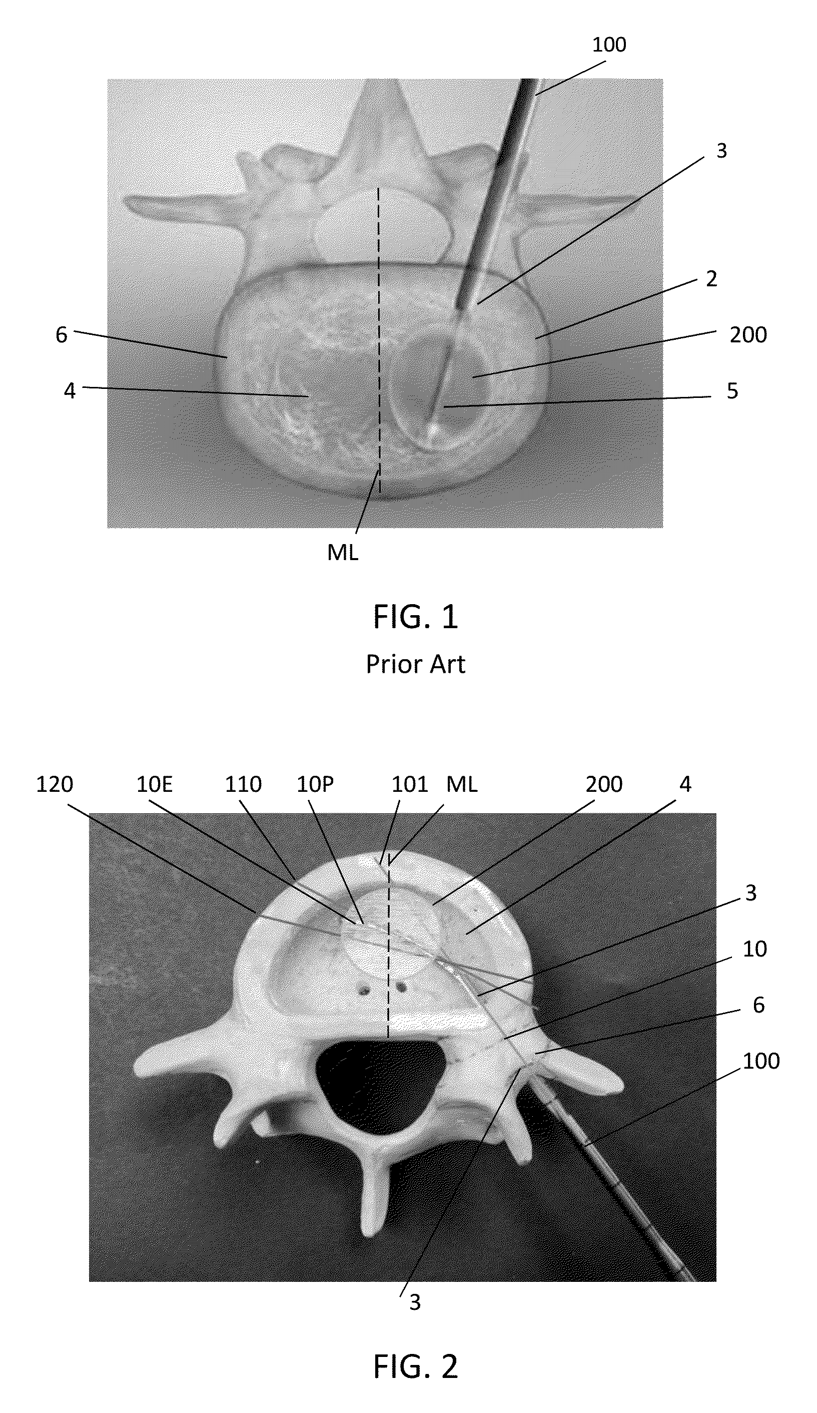
[0026]With reference to FIG. 1, a balloon tamp 200 is shown extending through a guide sleeve or cannula 100. The balloon tamp 200 is shown in an inflated condition. The balloon tamp 200 when expanded, compresses the soft tissue or cancellous bone 4 such that a void cavity 5 is created. When the straight line incision or opening 3 is created for the guide sleeve 100, it is known that the balloon tamp 200 when projecting inwardly on a straight line path is off center of the vertebrae. By being off the midline ML, the cavity 5 created is biased to the left or right side of the midline ML. As a result of this alignment relative to the midline ML, it is important that two openings are provided and a secondary procedure is applied on the opposite side (not illustrated). When that occurs, two cavities 5 are created to help stabilize the bone when bone cement or bone filler is added to the vertebral body 2 in a kyphoplasty procedure. By requiring two openings 3 to be created, the patient is...


PUM


Abstract

A tunneling device (10) for introduction into a body via a linearly extending guide (100) is formed as an elongated tunneling device (10) having an end portion (10E) bent to a predefined curvature. The elongated tunneling device (10) when confined in the linearly extending guide (100) is confined lengthwise in the guide (100). Upon movement of the tunneling device, advancing past the guide (100) into the body, the end portion (10E) of the tunneling device (10) returns to the predefined curvature without requiring any external physical resistance of load forces to initiate the bending.

Description

TECHNICAL FIELD[0001]The present invention relates to a device for use in treatment of acute vertebral compression fractures for introduction into a vertebral body through a single straight passage formed through cortical bone into the cancellous bone via a straight conduit or sleeve wherein the device when entering past the cancellous conduit or sleeve into the bone cavity transitions from straight to curved.BACKGROUND OF THE INVENTION[0002]Treatment of vertebral compression fractures commonly employs vertebroplasty and kyphoplasty techniques. Vertebroplasty employs a percutaneous injection of PMMA (polymethylmethacrylate) in a fractured vertebral body via a trocar and cannula.[0003]Kyphoplasty is a modification of percutaneous vertebroplasty. Kyphoplasty involves a preliminary step consisting of the percutaneous placement of an inflatable balloon tamp in the vertebral body. Inflation of the balloon creates a cavity in the bone prior to cement injection. The proponents of percutane...

Claims


Application Information

Patent Timeline
Patent Type & Authority Patents(United States)
IPC IPC(8): A61B17/00A61B17/16
CPCA61B17/1642A61B17/1671
Inventor MAHONEY, JOHNSTAUBLY, CHRISDICKERSON, CHASE
Owner SPINAL ELEMENTS INC
Why Eureka
Try Eureka