Squeezable container

a container and squeeze technology, applied in the field of squeezeable containers, can solve the problems of contaminating a surrounding portion of the pouring port, providing unsanitary conditions, etc., and achieve the effects of reducing the number of components, and ensuring the quality of the container

Active Publication Date: 2016-05-31
YOSHINO KOGYOSHO CO LTD
View PDF31 Cites 11 Cited by
  • Summary
  • Abstract
  • Description
  • Claims
  • Application Information

AI Technical Summary

Benefits of technology

[0012]According to the squeezable container of the present invention having the above construction, the partition wall blocking the communication of the mouth / neck portion to the pouring hole is disposed between the mouth / neck portion of the inner container part and the pouring hole of the pouring plug, and the valve body capable of opening the gate formed in the partition wall by pushing associated with the squeezing of the trunk portion of the outer container part to pass the content is disposed in the partition wall, and the reservoir for sucking back having an opening port passing through the partition wall and sucking and reserving the content retaining between the pouring hole and the partition wall in the recovering process of the trunk portion of the outer container part associated with the squeezing is disposed in the partition wall, so that the retained content is sucked into the reservoir by the movement of the movable body after the stop of the squeezing operation, whereby liquid dripping due to discharge of the content from the pouring port can be avoided. Also, the retained content is not flown into the container through the gate, so that the content in the container can be maintained at a high quality till the end of consumption.
[0013]Also, according to the squeezable container of the present invention, the squeezable container is constructed with the outer container part having the cylindrical mouth / neck portion and forming the appearance of the container, the inner container part arranged inside the outer container part and pouring the content filled therein through the pouring plug mounted on the mouth / neck portion by the volume reduction through the squeezing of the trunk portion of the outer container part, and the ambient air introducing valve for introducing ambient air between the outer container part and the inner container part in the recovering process of the trunk portion of the outer container part associated with the squeezing through the ambient air introducing hole formed in the pouring plug and the opening hole formed in the mouth / neck portion of the outer container part, so that the outer container part can rapidly recover to the initial form even in the crushing through squeezing.
[0014]Also, according to the squeezable container of the present invention, the ambient air introducing valve comprises a cantilever support elastic tongue piece integrally connected at its base portion to the valve body on the gate and separating from an inner wall valve seat of the pouring plug in the recovering process of the trunk portion of the outer container part to open the ambient air introducing hole, so that the number of components parts can be reduced and the efficient assembling can be attained.
[0015]Also, according to the squeezable container of the present invention, the ambient air introducing valve comprises a movable body, which blocks the ambient air introducing hole by matching with the ambient air introducing hole through tilting or reversing posture of the container or positive pressure generated between the outer container part and the inner container part while opens the ambient air introducing hole by separating from the ambient air introducing hole through negative pressure between the outer container part and the inner container part generated by normal posture of the container or recovering deformation of the outer container part, and at least two locking claws suspended downward along the edge portion of the ambient air introducing hole at the inner wall of the pouring plug to movably sandwich the movable body and introducing ambient air through a gap formed therebetween, so that the opening and closing of the ambient air introducing valve can be made more surely.
[0016]Further, according to the squeezable container of the present invention, the reservoir is constructed with a main reservoir body held at a suspended state in the lower part of the partition wall to form a housing space for the retained content at the inside thereof, and a slider capable of moving toward approaching and separating directions to the opening port in the housing space of the main reservoir body and sucking the retained content through the opening port into the housing space through the movement in the separating direction from the opening port, so that the retained content can be sucked into the housing space by a simple construction.
[0017]Moreover, according to the squeezable container of the present invention, the reservoir is constructed with a penetration pathway having a cylindrical body arranged to an adjacent site of the partition wall forming the gate and a spherical valve body capable of moving from exit side to entry side of the cylindrical body, and sucking and reserving the retained content in the space between the pouring hole and the partition wall in the recovering process of the trunk portion of the outer container part after finishing the squeezing, so that the retained content can be sucked into the housing space by a simple construction.

Problems solved by technology

Consequently, the retained content is flowed out by the posture of the container such as falling of the container or the like to cause liquid dripping, and hence there is a fear of contaminating a surrounding portion of the pouring port to provide unsanitary condition.

Method used


Image

  • Squeezable container
  • Squeezable container
  • Squeezable container

Examples


Embodiment Construction

[0030]The present invention will be described more concretely with reference of the accompanying drawings.

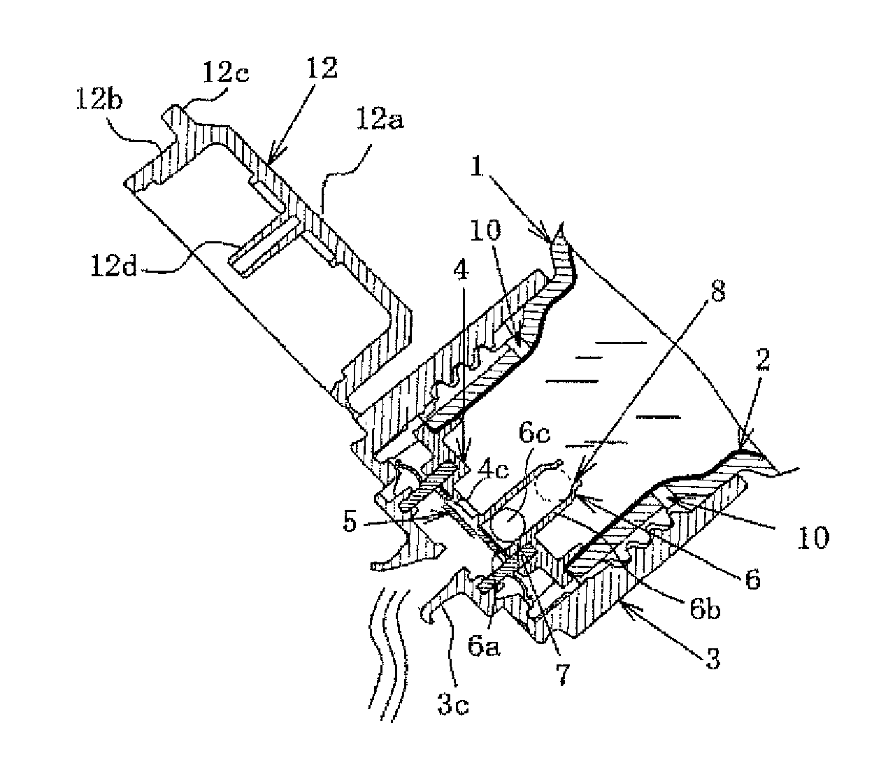
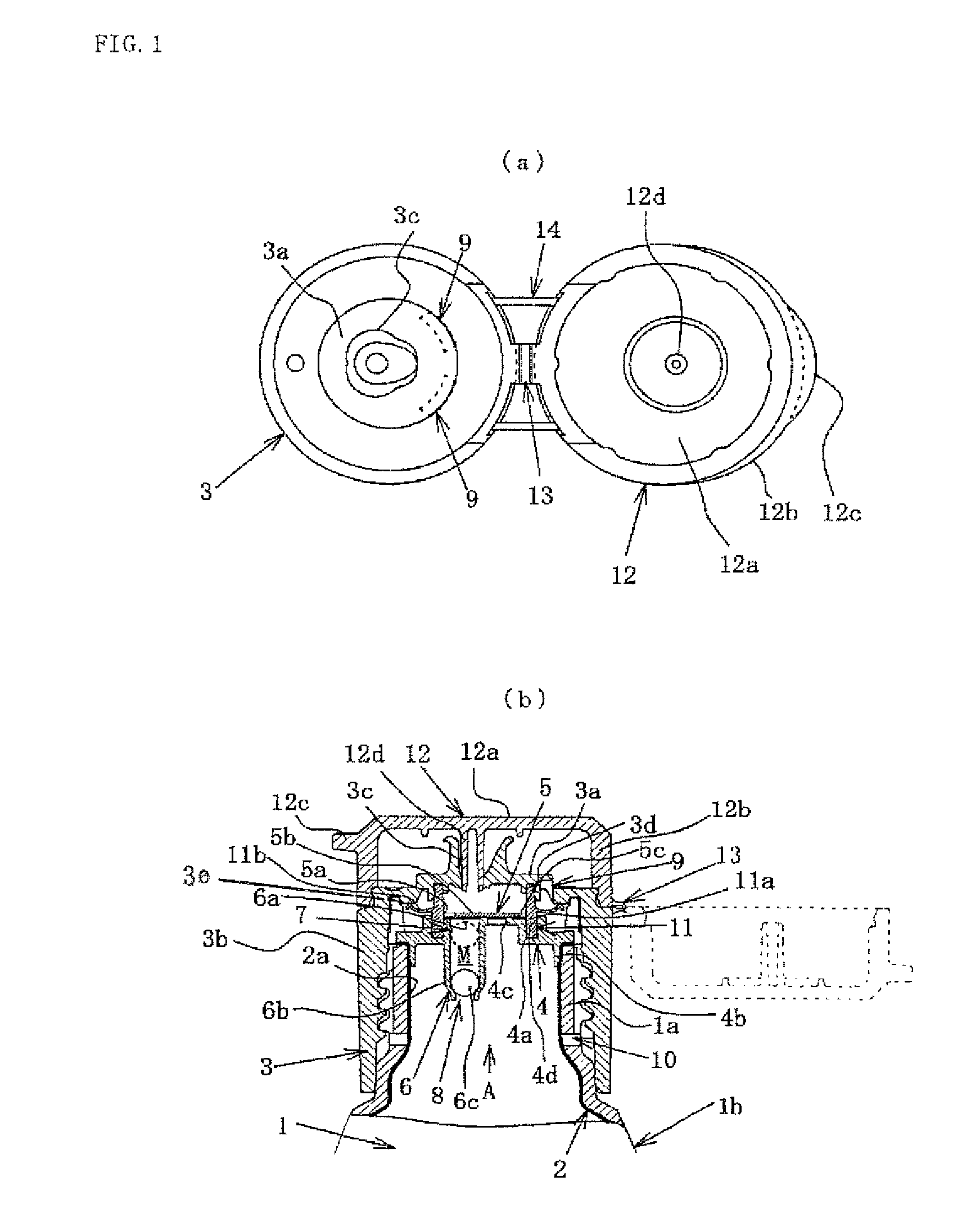
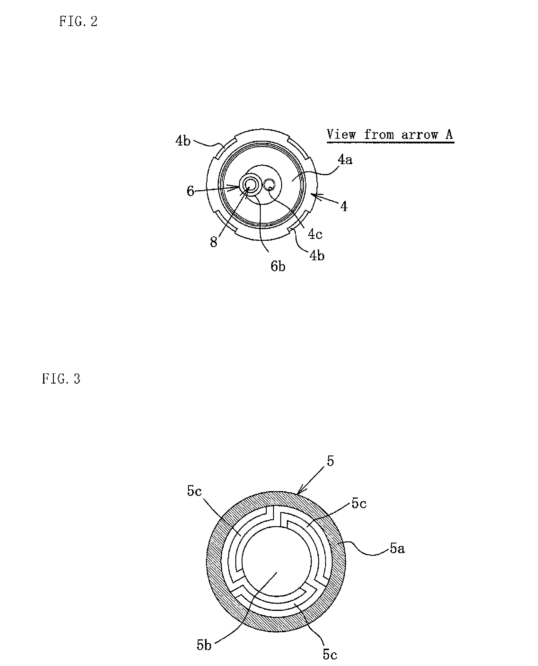
[0031]FIGS. 1(a) and (b) are schematic views of an embodiment of the squeezable container (delamination type) according to the present invention, and FIG. 2 is a view from an arrow A of FIG. 1.

[0032]In these figures, numeral 1 represents an outer container part (outer layer body) made from a soft synthetic resin recoverable to an initial form and forming an appearance of the container. The outer container part 1 may have, for example, a bottle form having a cylindrical mouth / neck portion 1a. However, the form of a trunk portion 1b thereof may be variously changed in accordance with the kind and applications of the content, so that the full form of the outer container part 1 is not denoted here. Although the cylindrical form is shown as an example of the mouth / neck portion 1a, the form is not restricted to the cylinder, and various forms may be adopted properly.

[0033]Numeral 2 re...


PUM

PropertyMeasurementUnit
volumeaaaaaaaaaa
pressureaaaaaaaaaa
timeaaaaaaaaaa

Abstract

A squeezable container is provided with an outer container for forming the outer appearance of the container, and having a mouth / neck section; and an inner container for discharging the contents filling the interior of the inner container through the spout plug mounted to the mouth / neck section when the volume of the inner container is reduced by squeezing the body section of the outer container, and positioned on the inside of the outer container.

Description

TECHNICAL FIELD[0001]This invention relates to a squeezable container made from a synthetic resin and having an inner-outer double structure. Here, the inner-outer double structure includes both of a double container formed by assembling an inner container part filled with a content onto an inside of an outer container part and a delamination type container wherein an inner layer body filled with a content is separated from an inner wall face of an outer layer body to pour the content. Hereinafter, the part located at the inside is represented as an inner container part and the part located at the outside is represented as an outer container part.RELATED ART[0002]In the squeezable container, the content is poured by pushing a trunk portion of the outer container part to reduce a volume of the inner container part disposed at an inside thereof. Since an inner pressure is decreased associated with the pouring of the content, only the trunk portion of the outer container part is restor...

Claims


Application Information

Patent Timeline
Patent Type & Authority Patents(United States)
IPC IPC(8): B65D35/46B65D1/32B65D83/48B65D23/02B65D77/04B65D83/62B65D47/08B65D81/24
CPCB65D83/62B65D1/32B65D23/02B65D47/0804B65D77/0486B65D81/24B65D83/48B65D47/40
Inventor HOSHINO, SHINYA
Owner YOSHINO KOGYOSHO CO LTD
Why Eureka
Try Eureka