

Imaging lens
a technology of imaging lens and peripheral area, applied in the field of imaging lenses, can solve the problems of low profile of imaging lens, difficult to correct peripheral area aberrations, etc., and achieve the effect of high brightness
- Summary
- Abstract
- Description
- Claims
- Application Information
AI Technical Summary
Benefits of technology
Problems solved by technology
Method used
Image

Examples
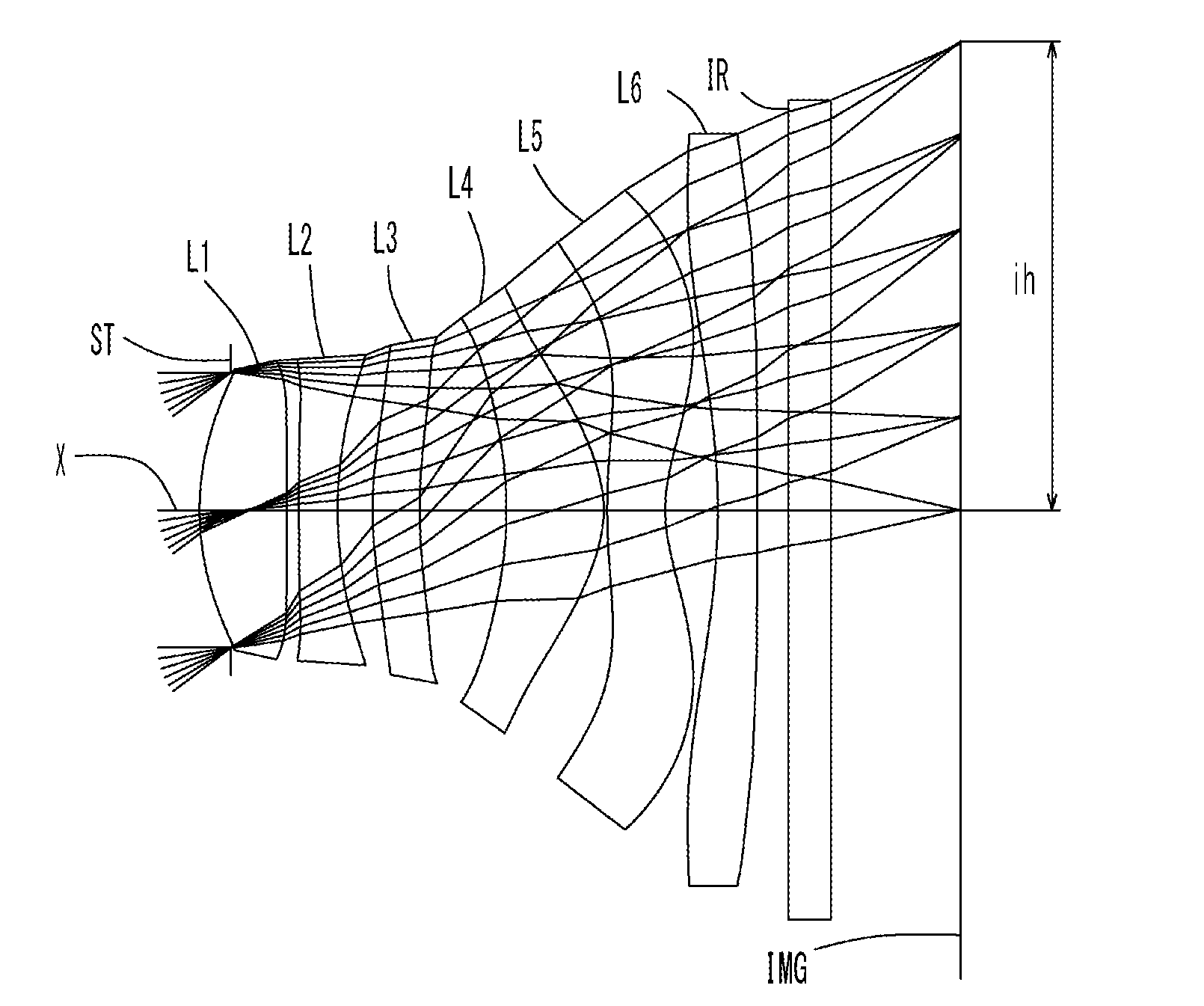
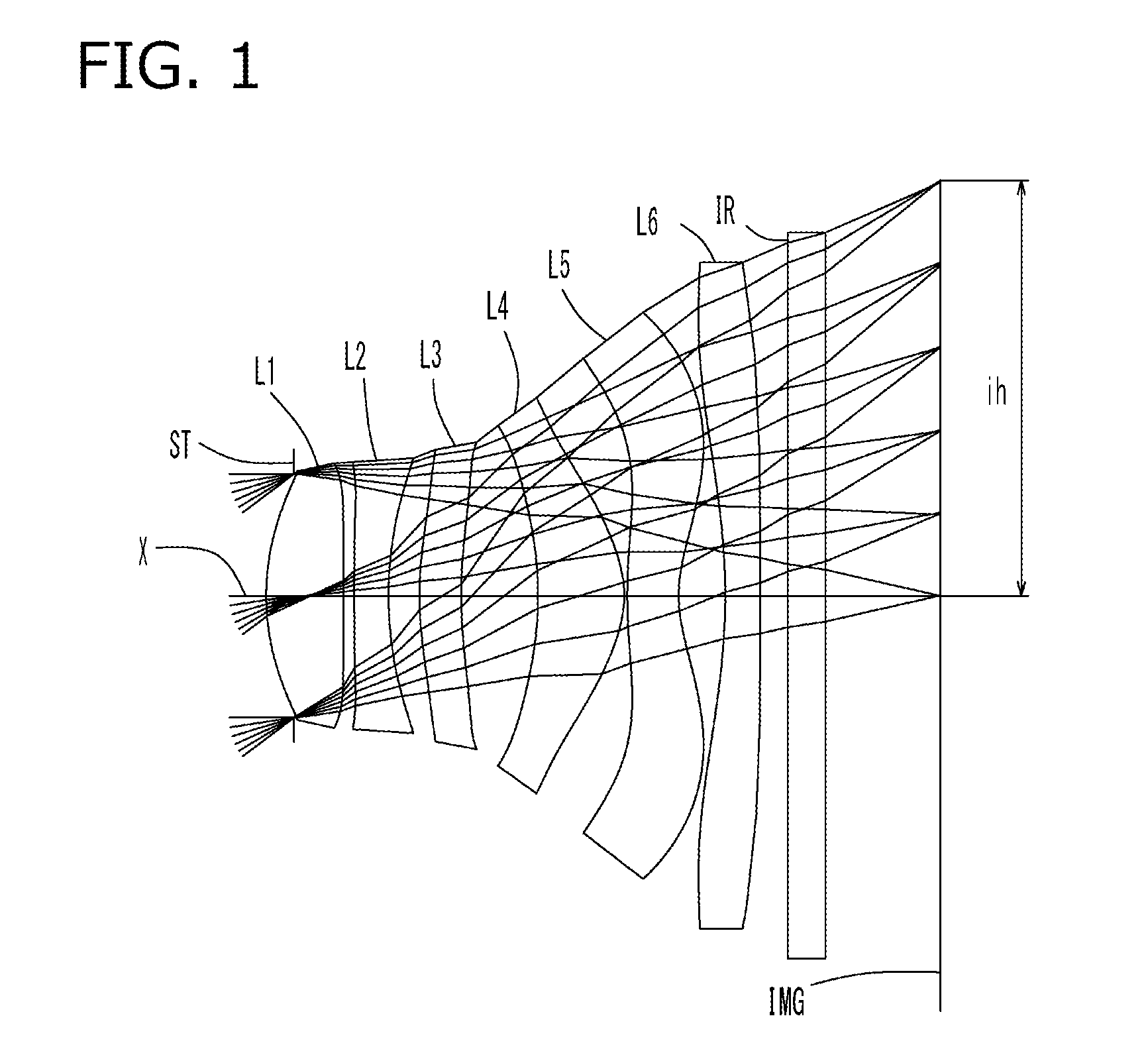
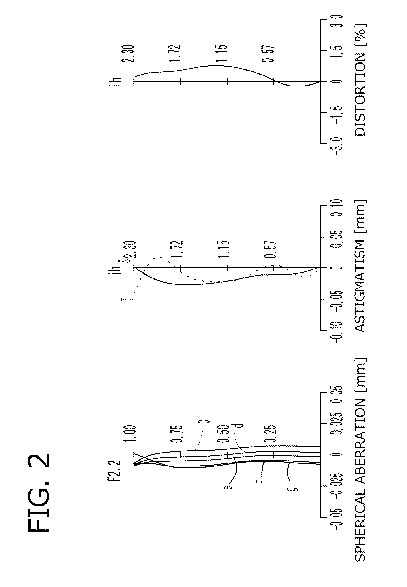
example 1
[0131]The basic lens data of Example 1 is shown in Table 1 below.
[0132]
TABLE 1Example 1in mmf = 3.03Fno = 2.2ω(°) = 37.0ih = 2.30TLA = 3.65b f = 0.92Surface DataCurvatureSurfaceRefractiveAbbeSurface No. iRadius rDistance dIndex NdNumber vd(Object Surface)InfinityInfinity 1 (Stop)Infinity−0.155 2*1.34210.4281.54455.57 3*27.17440.058 4*7.87000.1901.63523.91 5*1.81650.171 6*1.80160.2311.53556.16 7*2.60070.425 8*−1.92490.4771.54455.57 9*−0.61430.01710*2.79740.2851.53556.1611*0.71220.25812*−3.46430.1951.53556.1613*−89.99820.15014Infinity0.2101.51764.2015Infinity0.631Image PlaneInfinityConstituent Lens DataLensStart SurfaceFocal Length122.58124−3.765369.964481.471510−1.877612−6.745Aspheric Surface Data2nd Surface3rd Surface4th Surface5th Surface6th Surface7th Surfacek4.059E−010.000E+000.000E+00−1.901E+010.000E+000.000E+00A4−5.184E−02 −3.080E−01 −5.306E−01 −1.049E−01−4.490E−01 −1.814E−01 A66.259E−021.952E+003.570E+00 1.608E+004.557E−011.438E−02A8−5.653E−01 −7.994E+00 −1.227E+01 −4.242E+00−...
example 2
[0137]The basic lens data of Example 2 is shown in Table 3 below.
[0138]
TABLE 3Example 2in mmf = 3.04Fno = 2.2ω(°) = 37.0ih = 2.30TLA = 3.66bf = 0.83Surface DataCurvatureSurfaceRefractiveAbbeSurface No. iRadius rDistance dIndex NdNumber vd(Object Surface)InfinityInfinity 1 (Stop)Infinity−0.155 2*1.37120.4231.54455.57 3*49.19970.060 4*11.07520.1901.63523.91 5*1.87710.173 6*1.84650.2591.53556.16 7*3.04540.467 8*−2.05610.4561.54455.57 9*−0.65080.01510*2.59480.2941.53556.1611*0.73850.30012*−2.89050.1951.53556.1613*−90.00000.10014Infinity0.2101.51764.2015Infinity0.591Image PlaneInfinityConstituent Lens DataLensStart SurfaceFocal Length122.58624−3.588368.159481.571510−2.044612−5.590Aspheric Surface Data2nd Surface3rd Surface4th Surface5th Surface6th Surface7th Surfacek5.571E−010.000E+000.000E+00−2.084E+010.000E+000.000E+00A4−4.837E−02 −2.804E−01 −5.243E−01 −1.318E−01−4.676E−01 −1.808E−01 A64.875E−021.987E+003.689E+00 1.604E+004.493E−01−8.288E−03 A8−6.311E−01 −7.920E+00 −1.225E+01 −4.081E+0...
example 3
[0143]The basic lens data of Example 3 is shown in Table 5 below.
[0144]
TABLE 5Example 3in mmf = 3.04Fno = 2.2ω(°) = 37.0ih = 2.30TLA = 3.66bf = 0.83Surface DataCurvatureSurfaceRefractiveAbbeSurface No. iRadius rDistance dIndex NdNumber vd(Object Surface)InfinityInfinity 1 (Stop)Infinity−0.155 2*1.37130.4311.54455.57 3*−90.00000.058 4*14.50690.1901.63523.91 5*1.91200.177 6*1.95270.2581.53556.16 7*3.15120.443 8*−2.05310.4701.54455.57 9*−0.65430.01710*2.54560.2901.53556.1611*0.74990.30212*−2.71050.1951.53556.1613*−88.94840.10014Infinity0.2101.51764.2015Infinity0.592Image PlaneInfinityConstituent Lens DataLensStart SurfaceFocal Length122.48824−3.489368.934481.579510−2.107612−5.233Aspheric Surface Data2nd Surface3rd Surface4th Surface5th Surface6th Surface7th Surfacek5.659E−010.000E+000.000E+00−2.162E+010.000E+000.000E+00A4−4.803E−02 −2.772E−01 −5.245E−01 −1.352E−01−4.715E−01 −1.807E−01 A64.930E−021.992E+003.697E+00 1.603E+004.522E−01−5.912E−03 A8−6.383E−01 −7.914E+00 −1.223E+01 −4.061E+...
PUM
 Abstract
Description
Claims
Application Information