
Bidirectional data exchange circuit

a data exchange circuit and bidirectional technology, applied in logic circuits, electronic switching, pulse techniques, etc., can solve the problems of affecting the function safety, affecting the control of the direction signal for the buffer directly by a programmable component, and requiring a tedious manual operation

Inactive Publication Date: 2016-05-31
THALES SA
View PDF6 Cites 0 Cited by
  • Summary
  • Abstract
  • Description
  • Claims
  • Application Information

AI Technical Summary

Benefits of technology

The invention proposes a circuit that allows for secure and directional data transfer between devices. It has a feature that allows for a definitive selection of the data flow direction, ensuring that data is only transferred in the desired direction. The circuit also includes a mechanism to prevent any transfer between devices without an activation signal. Overall, this invention provides a more efficient and secure way to exchange data between devices.

Problems solved by technology

This solution however requires a tedious manual operation.
However this solution has bug risks, which is harmful to functional safety.
Indeed, the control of the direction signal for the buffer directly by a programmable component may be compromised by faulty software.
The use of specific logic components such as a flip-flop requires nomenclature management of a new type of components little used or not at all, which increases the cost of the electronic board.

Method used


Image

  • Bidirectional data exchange circuit
  • Bidirectional data exchange circuit
  • Bidirectional data exchange circuit

Examples


Embodiment Construction

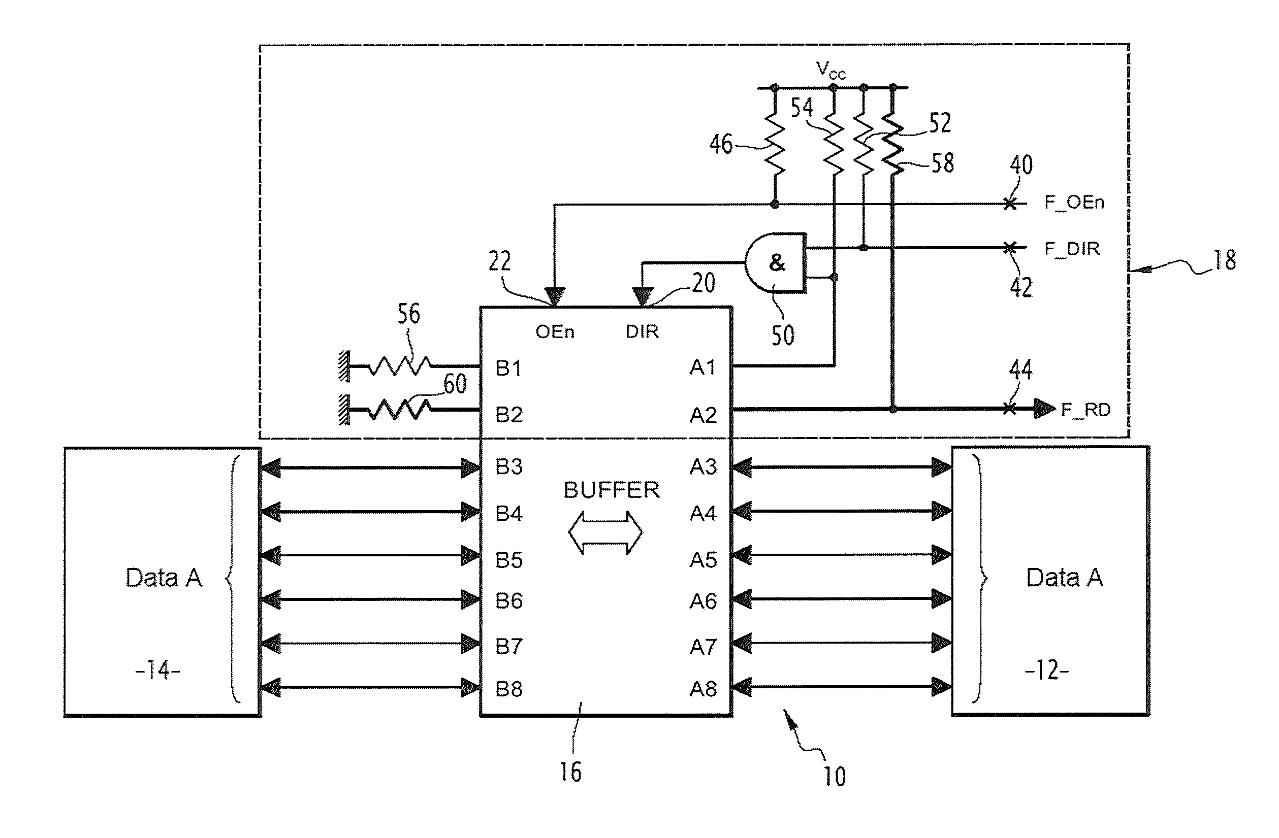
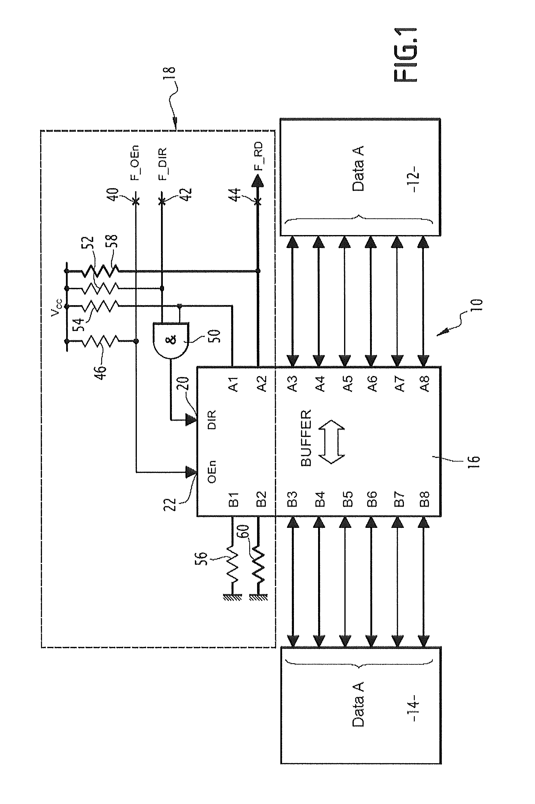
[0034]The bidirectional data exchange circuit 10 illustrated in FIG. 1 is for example applied between a processor 12 and a memory 14, and more generally between two electronic devices having to exchange data.

[0035]The exchange circuit 10 is able to allow, during a single initial phase, the transfer of data from the processor 12 towards the memory 14 and then after this initial transfer to only allow in future transfer of the data from the memory 14 note to the processor 12, without the processor being able to again write into the memory.

[0036]The circuit 10 includes a buffer or buffer memory 16. It further includes a circuit 18 for controlling the transfer direction of the data in the buffer 16.

[0037]This control module 18 only includes discrete passive elements, such as AND or OR logic gates and resistors.

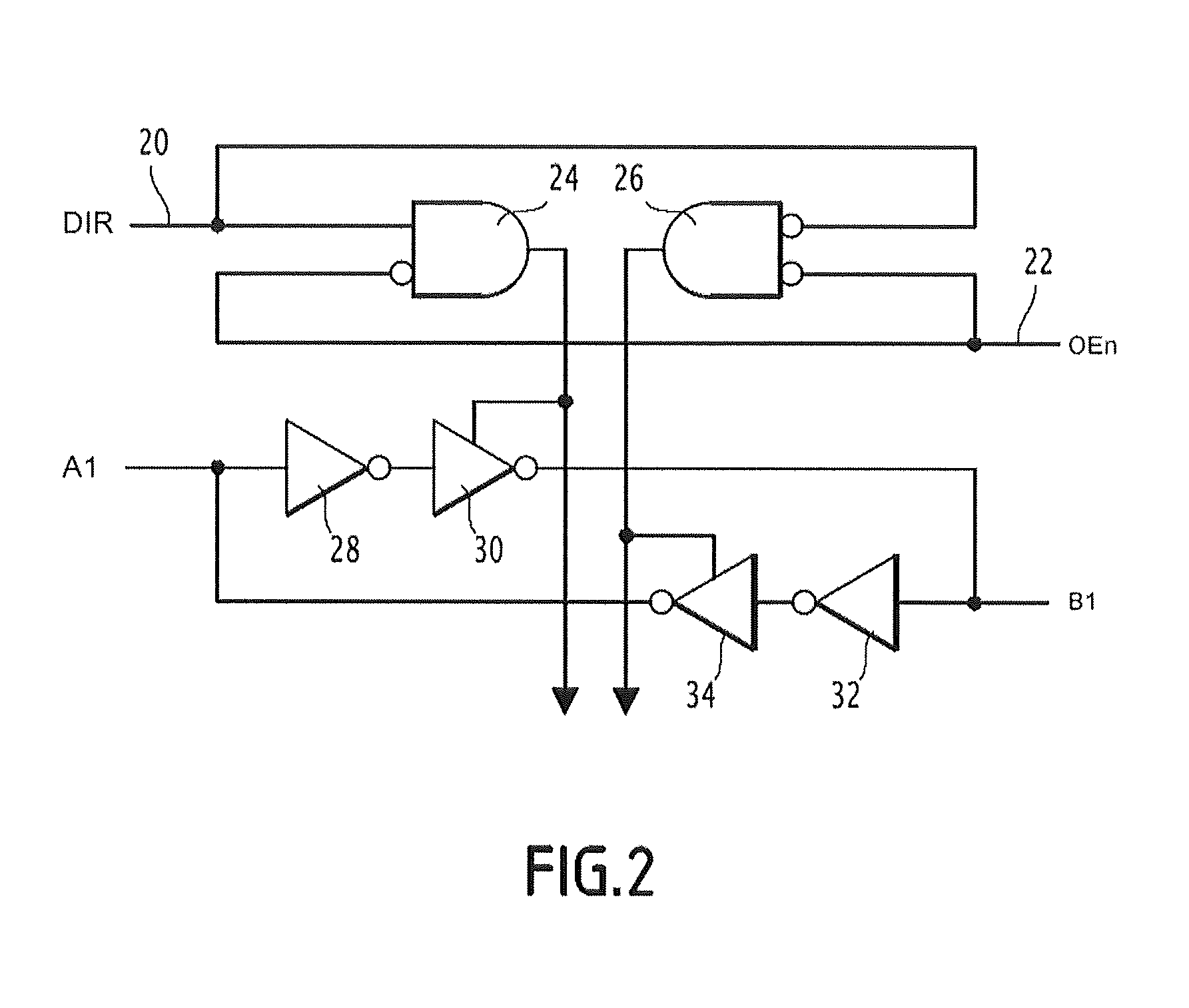
[0038]The buffer 16 includes, as this is known per se, two sets of two-by-two matched terminals per route allowing transfer of data from one terminal of a set to another matched t...


PUM


Abstract

A bidirectional data exchange circuit (10) includes a buffer (16) having paired terminals (A1 . . . A8, B1 . . . B8), a transfer direction input (20), an input (42) for controlling the transfer direction, and a logic gate (50). In the logic gate (50), the output is connected to the transfer direction input (20), an input is connected to the input (42) for controlling the transfer direction, this input being further connected to a first reference potential (Vcc) through a resistor (52), and the other input is connected to a terminal (A1) of the buffer (16) and to the first reference potential (Vcc) through a resistor (54; 154), and the terminal (B1) of the buffer (16), matched with the terminal (A1) of the buffer to which is connected the other input of the logic gate (50) being connected to a second reference potential through a resistor (56). The order of the first and second reference potentials and the nature of the logic gate (50) are such that, after a first transfer direction control of the buffer in one direction, the matched terminals (A1) force the logic gate (50) into a predetermined state independent of the value of the signal on the direction control input (42).

Description

CROSS-REFERENCE TO RELATED APPLICATIONS[0001]This application claims benefit (under 35 USC 119(e)) of French Application Serial No. 12-03440, filed Dec. 17, 2012, which is incorporated herein by reference in its entirety.TECHNICAL FIELD AND STATE OF THE ART[0002]The present invention relates to a bidirectional data exchange circuit including:[0003]a buffer including:[0004]a first set of terminals and a second set of terminals, for which the terminals are paired two by two for bidirectional data exchange between two paired terminals of the two sets;[0005]an input in the direction of transfer between two paired terminals from one input to one output, the input being placed at a high impedance in the absence of any voltage on these terminals;[0006]an input for controlling the transfer direction.[0007]In certain digital electronic boards having safety PLCs, for example in railway signaling circuits, it is necessary to allow initial writing of data through a buffer or buffer memory, and ...

Claims


Application Information

Patent Timeline
Patent Type & Authority Patents(United States)
IPC IPC(8): H03K17/00H03K19/00G06F13/40
CPCH03K19/0002G06F13/4072
Inventor PUBERT, LAURENTPICHET, JEROMEGRIMONPREZ, BENJAMINCOLLANGE, THIERRY
Owner THALES SA
Learn More