Pilot fuel injector with swirler

a pilot injector and swirler technology, applied in the field of pilot injectors, can solve the problems of weakening, weakening, spreading of strong swirling air flow from the main injector, etc., and achieve the effects of ignitability, flame holding performance, and combustion efficiency without deteriorating the combustion efficiency of the pilot injector

Active Publication Date: 2016-06-14
KAWASAKI HEAVY IND LTD +1
View PDF18 Cites 7 Cited by
  • Summary
  • Abstract
  • Description
  • Claims
  • Application Information

AI Technical Summary

Benefits of technology

[0008]The present invention addresses the above described conditions, and an object of the present invention is to provide a fuel injector capable of improving the combustion efficiency, ignitability, and flame holding performance of the pilot injector when the output of the gas turbine engine is low, without largely separating the pilot combustion region and the main combustion region from each other.

Problems solved by technology

However, the strong swirling air flow from the main injector spreads, decays, and weakens as it flows toward the downstream side.

Method used


Image

  • Pilot fuel injector with swirler
  • Pilot fuel injector with swirler
  • Pilot fuel injector with swirler

Examples


Embodiment Construction

[0035]Hereinafter, preferred embodiments of the present invention will be explained in reference to the drawings.

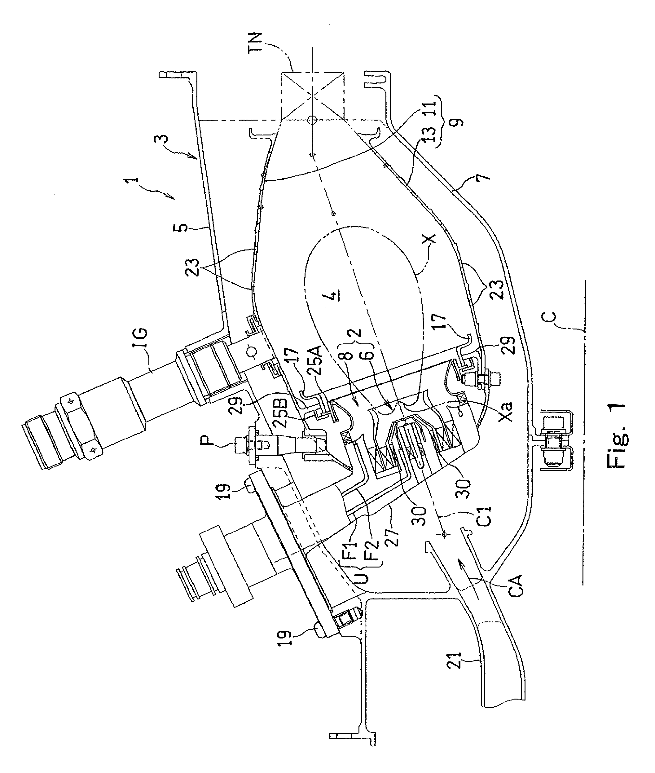
[0036]FIG. 1 shows a combustor 1 of a gas turbine engine including a fuel injector 2 according to one embodiment of the present invention. The combustor 1 mixes fuel with compressed air supplied from a compressor (not shown) of the gas turbine engine, combusts the obtained mixture, and supplies a high temperature and pressure combustion gas, generated by this combustion, to drive the turbine.

[0037]The combustor 1 is an annular type, and an annular outer casing 5 and an annular inner casing 7 provided inside the annular outer casing 5 constitute a combustor housing 3 including an annular internal space. The annular outer casing 5 and the annular inner casing 7 are provided coaxially with an engine rotation central axis C. In the annular internal space of the combustor housing 3, an annular combustor liner 9 is provided coaxially with the combustor housing 3. The combustor ...


PUM


Abstract

A fuel injector includes: a pilot injector configured to spray fuel so as to form a first combustion region in a combustion chamber; and a main injector provided coaxially with the pilot injector so as to surround the pilot injector and configured to supply a fuel-air mixture that is a mixture of the fuel and air to form a second combustion region in the combustion chamber, wherein the pilot injector includes: a center nozzle configured to eject air jet flowing straight in an axial direction on a central axis of the pilot injector; an inside swirler provided on a radially outer side of the center nozzle and configured to cause inflow air to swirl around the central axis; and a pilot fuel injecting portion configured to inject the fuel from between the center nozzle and the inside swirler to air flow in the center nozzle.

Description

BACKGROUND OF THE INVENTION[0001]1. Field of the Invention[0002]The present invention relates to a fuel injector used in, for example, a gas turbine engine and including a combined fuel injector configured by combining a plurality of fuel injectors, and particularly to a pilot injector.[0003]2. Description of the Related Art[0004]In recent years, in consideration of the environment, there is a need for a reduction of NOx (nitrogen oxide) emitted from gas turbine engines. The NOx to be emitted from the gas turbine engine is generated mainly by oxidization of nitrogen in inflow air when fuel is supplied to the inflow air and combusted at high temperature. Meanwhile, the amount of CO2 emission of the gas turbine engine, that is, fuel consumption decreases as an exhaust gas at an exit of a combustor increases in temperature. Therefore, to reduce the CO2, the fuel needs to be combusted at high temperature by increasing a fuel-air ratio. According to a fuel nozzle of a combustor of a conv...

Claims


Application Information

Patent Timeline
Patent Type & Authority Patents(United States)
IPC IPC(8): F23R3/34F23R3/28
CPCF23R3/343F23R3/286
Inventor MATSUYAMA, RYUSUKEKOBAYASHI, MASAYOSHIODA, TAKEOHORIKAWA, ATSUSHIHAYASHI, SHIGERUSHIMODAIRA, KAZUOMATSUURA, KAZUAKIYAMADA, HIDESHIKUROSAWA, YOUJIFUJIWARA, HITOSHI
Owner KAWASAKI HEAVY IND LTD
Why Eureka
Try Eureka