Supercharge Your Innovation With Domain-Expert AI Agents!

Ignition plug and ignition system

a technology of ignition system and ignition plug, which is applied in the direction of sparking plugs, combustion process, lighting and heating apparatus, etc., can solve the problems of limited expansion of flame, ground electrode consumption locally, and hinder plasma growth, so as to promote plasma growth, increase the ratio of spark discharge generation at the remote side edge portion, and reduce the effect of spark discharge generation at the near side edge portion

Active Publication Date: 2016-06-14
NGK SPARK PLUG CO LTD
View PDF13 Cites 0 Cited by
  • Summary
  • Abstract
  • Description
  • Claims
  • Application Information

AI Technical Summary

Benefits of technology

The present invention provides an ignition plug with a center electrode、 insulator, metallic shell, and ground electrode that can apply multiple peak voltages to the center electrode to promote plasma growth and expand flame. The ignition system includes a voltage supply section that supplies the voltage for trigger discharge and peak voltages to the center electrode. This technology enhances the overall spark-consumption resistance of the ignition plug and promotes ignition.

Problems solved by technology

Therefore, these ignition plugs have a problem in that, when trigger discharge occurs at a position near the bent portion of the ground electrode, the growth of plasma is hindered by the ground electrode, and expansion of flame is restricted.
Also, the ignition plug disclosed in Patent Document 3 has a problem in that, since trigger discharge occurs, in a concentrated manner, on a surface of the ground electrode which faces the center electrode, the ground electrode consumes locally, and the overall spark-consumption resistance of the ground electrode deteriorates.

Method used


Image

  • Ignition plug and ignition system
  • Ignition plug and ignition system
  • Ignition plug and ignition system

Examples


first embodiment

A.

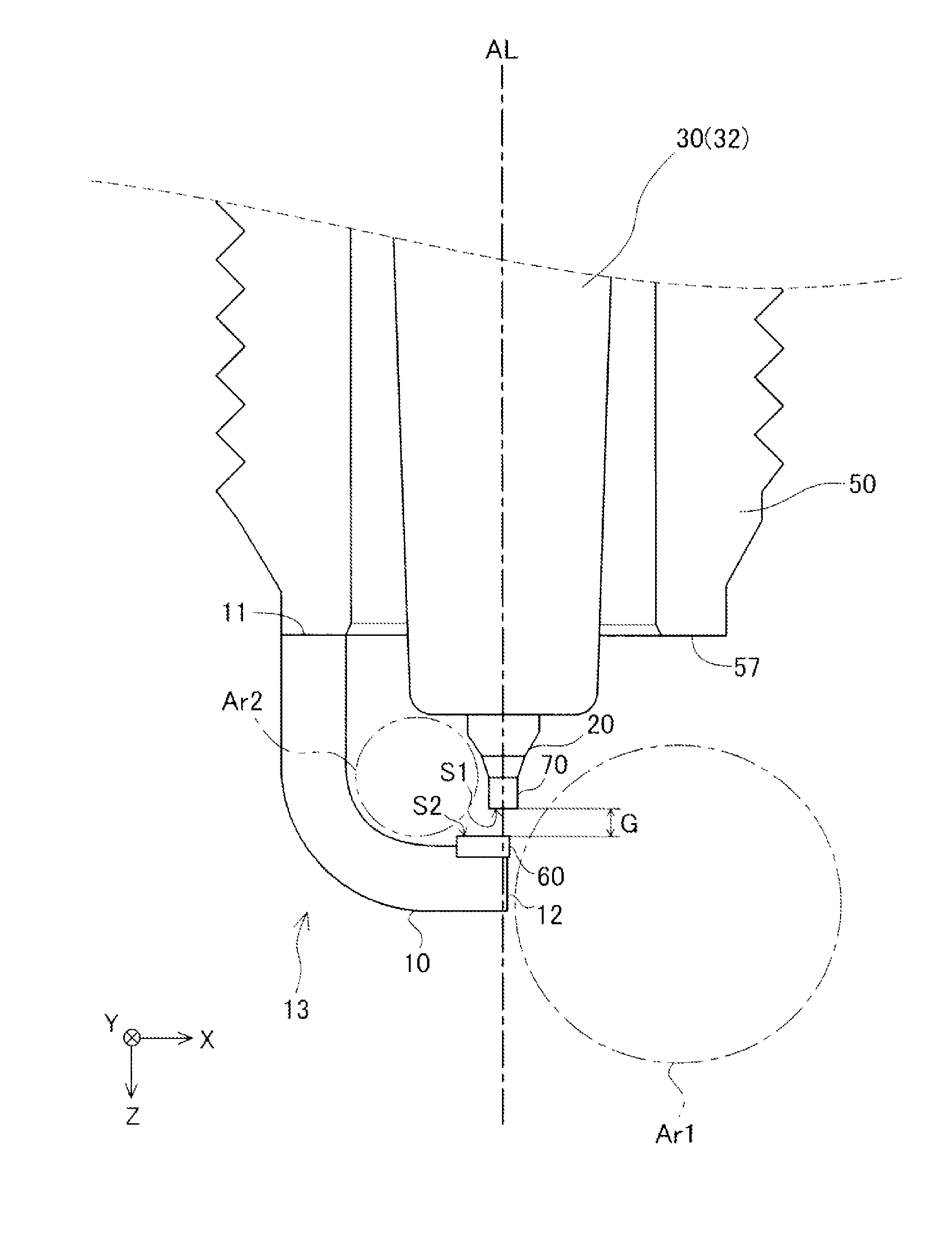
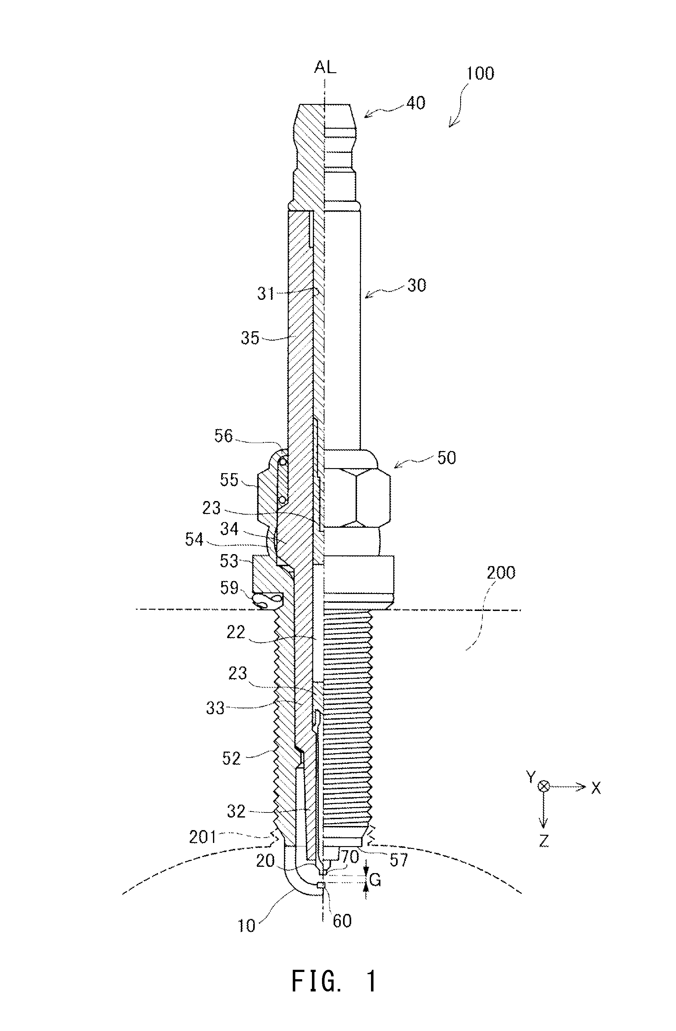
[0042]FIG. 1 is a partially sectioned view of an ignition plug which is one embodiment of the present invention. In a first embodiment, the ignition plug 100 is also called “spark plug” and is used in, for example, an engine of a vehicle. In FIG. 1, an external shape of the ignition plug 100 is shown on the right side of an axial line AL, which is the center axis of the ignition plug 100, and a cross-sectional shape of the ignition plug 100 is shown on the left side of the axial line AL. In the following description, the lower side of FIG. 1 (the side of the ignition plug 100 where a ground electrode 10 to be described later is disposed) will be referred to as the “forward end side,” and the upper side of FIG. 1 (the side of the ignition plug 100 where a metallic terminal 40 to be described later is disposed) will be referred to as the “rear end side.”

[0043]The ignition plug 100 includes a center electrode 20, a ceramic insulator 30, the metallic terminal 40, a metallic shell 50, ...

second embodiment

B.

[0076]FIG. 6 is an explanatory view showing projection of the forward end surface and the facing end surface onto the plane orthogonal to the axial direction in an ignition plug of a second embodiment. The ignition plug of the second embodiment is identical with the ignition plug 100 of the first embodiment except that the shape of the projection of the facing end surface (the electrode tip) is hexagonal.

[0077]As shown in FIG. 6, the projection P2a of the facing end surface in the second embodiment has a hexagonal peripheral shape (contour). Specifically, the projection P2a has a short side L24 located at the −X direction side end of the projection P2a and extending along the Y-axis direction, a short side L21 located at the +X direction side end of the projection P2a and extending along the Y-axis direction, a long side L25 located at the −Y direction side end of the projection P2a and extending along the X-axis direction, a long side L26 located at the +Y direction side end of t...

third embodiment

C.

[0081]FIG. 7 is an explanatory view showing projection of the forward end surface and the facing end surface onto the plane orthogonal to the axial direction in an ignition plug of a third embodiment. The ignition plug of the third embodiment is identical with the ignition plug 100 of the first embodiment except that the entirety of the projection of the facing end surface (the electrode tip) is located within the projection of the forward end surface S1.

[0082]As shown in FIG. 7, like the projection P2 in the first embodiment, the projection P2b of the facing end surface in the third embodiment has a rectangular peripheral shape (contour). Specifically, the projection P2b of the facing end surface has a short side L31 located at the +X direction side end of the projection P2b and extending along the Y-axis direction, a short side L32 located at the −X direction side end of the projection P2b and extending along the Y-axis direction, a long side L33 located at the −Y direction side...


PUM


Abstract

An ignition plug that promotes expansion of flame and enhances spark corrosion resistance, said plug includes a center electrode; a tubular insulator holding the center electrode; a tubular metallic shell holding the insulator; and a ground electrode having a bent portion and a facing end surface. A plurality of peak voltages can be applied to the center electrode after application of a voltage for trigger discharge thereto. When a forward end surface of the center electrode and the facing end surface are projected onto a plane orthogonal to axial direction of the center electrode, the projection of the center of the forward end surface and the projection of the facing end surface overlap with each other, and the projection of a remote-side edge portion of the facing end surface which is located on the side remote from the bent portion is located within the projection of the forward end surface.

Description

FIELD OF THE INVENTION[0001]The present invention relates to an ignition plug.BACKGROUND OF THE INVENTION[0002]An ignition plug used for an internal combustion engine of, for example, of a vehicle includes a center electrode, and a ground electrode which has a bent portion and is disposed to face the center electrode. In order to enhance the ignition performance of such an ignition plug, there has been proposed a method of generating plasma on the basis of spark discharge (trigger discharge) to thereby expand flame (See WO2012 / 111700 A2, WO2012 / 111701 A2 and Japanese Patent Application Laid-Open (kokai) No. 2010-102864; hereinafter respectively referred to as Patent Documents 1 through 3).[0003]However, in the case of the ignition plugs disclosed in Patent Documents 1 and 2, trigger discharge occurs not only at the distal end of the ground electrode but also at a position near a bent portion of the ground electrode at a high ratio. Therefore, these ignition plugs have a problem in t...

Claims


Application Information

Patent Timeline
Patent Type & Authority Patents(United States)
IPC IPC(8): F23Q3/00H01T13/20
CPCH01T13/20
Inventor BAN, KENJINAKAYAMA, KATSUTOSHI
Owner NGK SPARK PLUG CO LTD
Features
  • R&D
  • Intellectual Property
  • Life Sciences
  • Materials
  • Tech Scout
  • Unparalleled Data Quality
  • Higher Quality Content
  • 60% Fewer Hallucinations
Learn More