Sliding parts

a sliding part and relative rotation technology, applied in the direction of engine seals, mechanical equipment, engine components, etc., can solve the problems of fluid film thickening, leakage of fluid outflow, and lack of seal integrity control elements, so as to reduce sliding resistance, improve sliding properties, stable sliding properties

Active Publication Date: 2016-06-21
EAGLE INDS
View PDF20 Cites 9 Cited by
  • Summary
  • Abstract
  • Description
  • Claims
  • Application Information

AI Technical Summary

Benefits of technology

[0033](1) In accordance with the first aspect, leakage is prevented when the sliding parts are stopped, and sufficient lubrication during periods of low speed when rotation commences is possible, enabling sliding resistance to be reduced and stable sliding properties to be obtained. In addition, a sufficient lubricant film is formed by the sealed fluid between the sealing faces, allowing for improved sliding properties. Moreover, leakage of the sealed fluid from the sealing faces when dynamic pressure is being generated can be controlled by the pumping action of the pumping areas, allowing for seal integrity to be controlled.
[0034](2) In accordance with the second aspect, a sealed fluid flow from the sealed fluid side between the sealing faces back to the sealed fluid side is formed, thereby preventing excessive leakage during rotation, and improving seal properties.
[0035](3) In accordance with the third aspect, pumping can be easily formed, and pumping performance can be modified by modifying the angle of inclination.
[0036](4) The fourth aspect allows for application in cases in which the sealing faces rotate in two directions.
[0037](5) In the fifth aspect, both the directionality and machining position of the periodic linear indentation structure of the pumping areas can be controlled, enabling a desired periodic linear indentation structure to be formed within each of discontinuous small divisions.
[0038](6) In accordance with the sixth aspect, seal integrity control can be optimized, allowing for maximum improvement of seal properties.

Problems solved by technology

However, in such cases, positive pressure is generated between the sealing faces, so that the fluid escapes from the positive pressure portion outside of the sealing faces.
Such fluid outflow constitutes leakage in the case of a seal.
However, the dynamic pressure-generating groove 32 of the prior art has a shape for creating a dynamic pressure effect, and does not have an element for controlling seal integrity.
Thus, there is the problem that, while dynamic pressure is generated by the dynamic pressure-generating groove 32 when the mating ring and a seal ring constituting the sliding parts rotate relative to each other, the generation of the dynamic pressure causes the fluid film to thicken, and the sealing faces of the mating ring and the seal ring break contact, so that, while sliding resistance decreases, leakage increases.
There is also the problem that, for this reason, sufficient quantities of sealed fluid cannot be introduced between the sealing faces during the period from when rotation begins until dynamic pressure is generated, leading to reduced lubrication and increased torque, in turn leading to the problems of seizing, vibration, noise, and the like being generated and sliding properties becoming unstable.
Examples of prior art in which dynamic pressure-generating grooves are provided in order to prevent wear during sliding part rotation are known (for example, see patent document 2), but, because these examples lack an element for controlling seal integrity, like the prior art described above, they have the problem of increased leakage.

Method used


Image

  • Sliding parts
  • Sliding parts
  • Sliding parts

Examples


embodiment 1

[0054]{Embodiment 1}

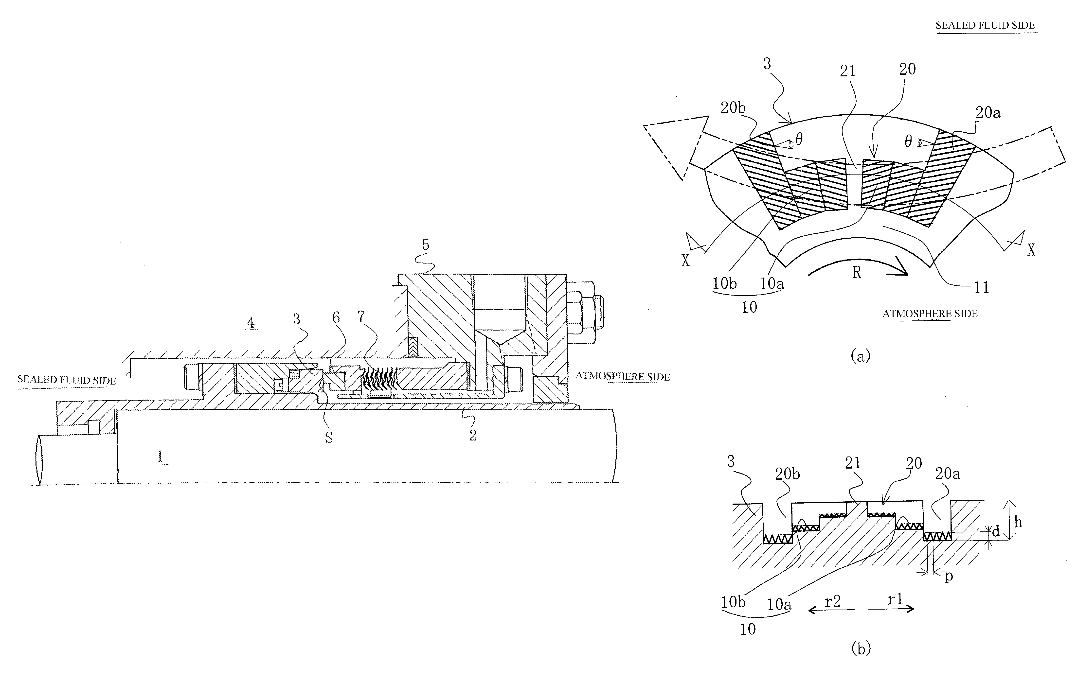
[0055]FIG. 3 is an illustration of dynamic pressure-generating grooves and pumping areas formed in a sealing face of a rotating ring according to a first embodiment of the present invention, with FIG. 3(a) being a plan view thereof and FIG. 3(b) being a cross-sectional view along line X-X in FIG. 3(a).

[0056]In FIG. 3, the rotating ring 3 is referred to as a mating ring, and is often formed from SiC (a hard material). A plurality of dynamic pressure-generating grooves 20 is discontinuously formed in the circumferential direction of the sealing face S of the rotating ring 3. The dynamic pressure-generating grooves 20 are formed so that, taking one pair of adjacent radial grooves 20a, 20b as a single group, the radial grooves making up the plurality of dynamic pressure-generating groove groups have tapered shapes tapering in opposite directions with respect to the circumferential direction so as to increase in height as they approach a boundary therebetween, and dam...

embodiment 2

[0086]{Embodiment 2}

[0087]FIG. 4 is an illustration of dynamic pressure-generating grooves and pumping area formed in a sealing face of a rotating ring according to a second embodiment of the present invention, with FIG. 4(a) being a plan view thereof and FIG. 4(b) being a cross-sectional view along line Y-Y in FIG. 4(a).

[0088]In FIG. 4, numbers identical to those in FIG. 3 indicate identical parts of FIG. 3; redundant description of these will be omitted.

[0089]The dynamic pressure-generating grooves 20 shown in FIG. 4(a) extend roughly in the radial direction of the sealing face S of the rotating ring 3 from an outer circumferential end towards the inner circumference thereof, and bend in the inner circumferential side to form roughly L-shaped grooves extending roughly in the circumferential direction. The dynamic pressure-generating grooves 20 communicate with the sealed fluid side at the outer circumference of the rotating ring 3, and are configured so as to readily draw the seal...


PUM


Abstract

Sliding parts are provided where a plurality of dynamic pressure-generating grooves for generating dynamic pressure via the relative rotational sliding of the stationary ring and the rotating ring are formed in a circumferential direction on a sealing face of one of a stationary ring and the rotating ring so as to communicate with a sealed fluid-containing space, and pumping areas for generating pumping action via the relative rotational sliding of the stationary ring and the rotating ring are formed within the dynamic pressure-generating grooves.

Description

[0001]This application is the U.S. National Phase under 35 U.S.C. §371 of International Application PCT / JP2012 / 070646, filed Aug. 13, 2012, which claims priority to Japanese Patent Application No. 2011-197732, filed Sep. 10, 2011. The International Application was published under PCT Article 21(2) in a language other than English.TECHNICAL FIELD[0002]The present invention relates to relatively rotating sliding parts, and in particular to sliding parts used, for example, in the field of automotive seals, general industrial mechanical seals, and other types of mechanical seals.BACKGROUND ART[0003]In sealing apparatus for preventing the leakage of a sealed fluid, such apparatus comprising two parts configured so as to rotate relatively to one another and so that end surfaces thereof slide along a plane, such as, for example, a mechanical seal, a balance must be struck between the two opposing conditions of seal tightness and lubrication in order to maintain seal integrity for extended ...

Claims


Application Information

Patent Timeline
Patent Type & Authority Patents(United States)
IPC IPC(8): F16J15/34F16J15/40
CPCF16J15/34F16J15/3404F16J15/3408F16J15/3412F16J15/3424F16J15/3428F16J15/40
Inventor HOSOE, TAKESHIINOUE, HIDEYUKI
Owner EAGLE INDS
Why Eureka
Try Eureka