Light emitting element including first electrode with first connecting portion and first extending portion, and second electrode with second connecting portion and two second extending portions

a technology of light emitting elements and connecting parts, which is applied in the direction of semiconductor devices, electrical apparatus, transistors, etc., can solve the problems of insufficient emission, increase of forward voltage (vf), and decrease of emission efficiency, so as to achieve further improvement of emission efficiency

Active Publication Date: 2016-06-21
NICHIA CORP
View PDF24 Cites 8 Cited by
  • Summary
  • Abstract
  • Description
  • Claims
  • Application Information

AI Technical Summary

Benefits of technology

[0008]Accordingly, one aspect of this disclosure is devised to solve the problems as described above, and is aimed to provide a light emitting element having higher emission efficiency by reducing uneven distribution of the current density between the electrodes, or the like.
[0010]With the light emitting element according to the various embodiments of the present invention, the emission efficiency can be further improved.

Problems solved by technology

However, in reality, even with those structures, a deviation in the distribution of current density between the second electrode and the first electrode occurs, which may lead to problems such as an increase in forward voltage (Vf), insufficient for obtaining a uniform emission, and / or a decrease in emission efficiency, etc.
Also, depending on the arrangement of the second electrode and the first electrode, and further on the type of the connection of those electrodes to outside, wires which impede overall emission may present over the light emitting element with a relatively long distance, which may result in a decrease in the light extraction efficiency.
The wires arranged over the light emitting element decrease in height from the respective bonding points on the light emitting element toward the outer periphery of the light emitting element which may cause contact of the wires with the outer periphery of the light emitting element, which results in short circuit.

Method used


Image

  • Light emitting element including first electrode with first connecting portion and first extending portion, and second electrode with second connecting portion and two second extending portions
  • Light emitting element including first electrode with first connecting portion and first extending portion, and second electrode with second connecting portion and two second extending portions
  • Light emitting element including first electrode with first connecting portion and first extending portion, and second electrode with second connecting portion and two second extending portions

Examples


embodiment 1

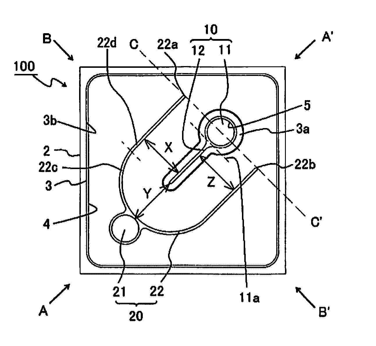
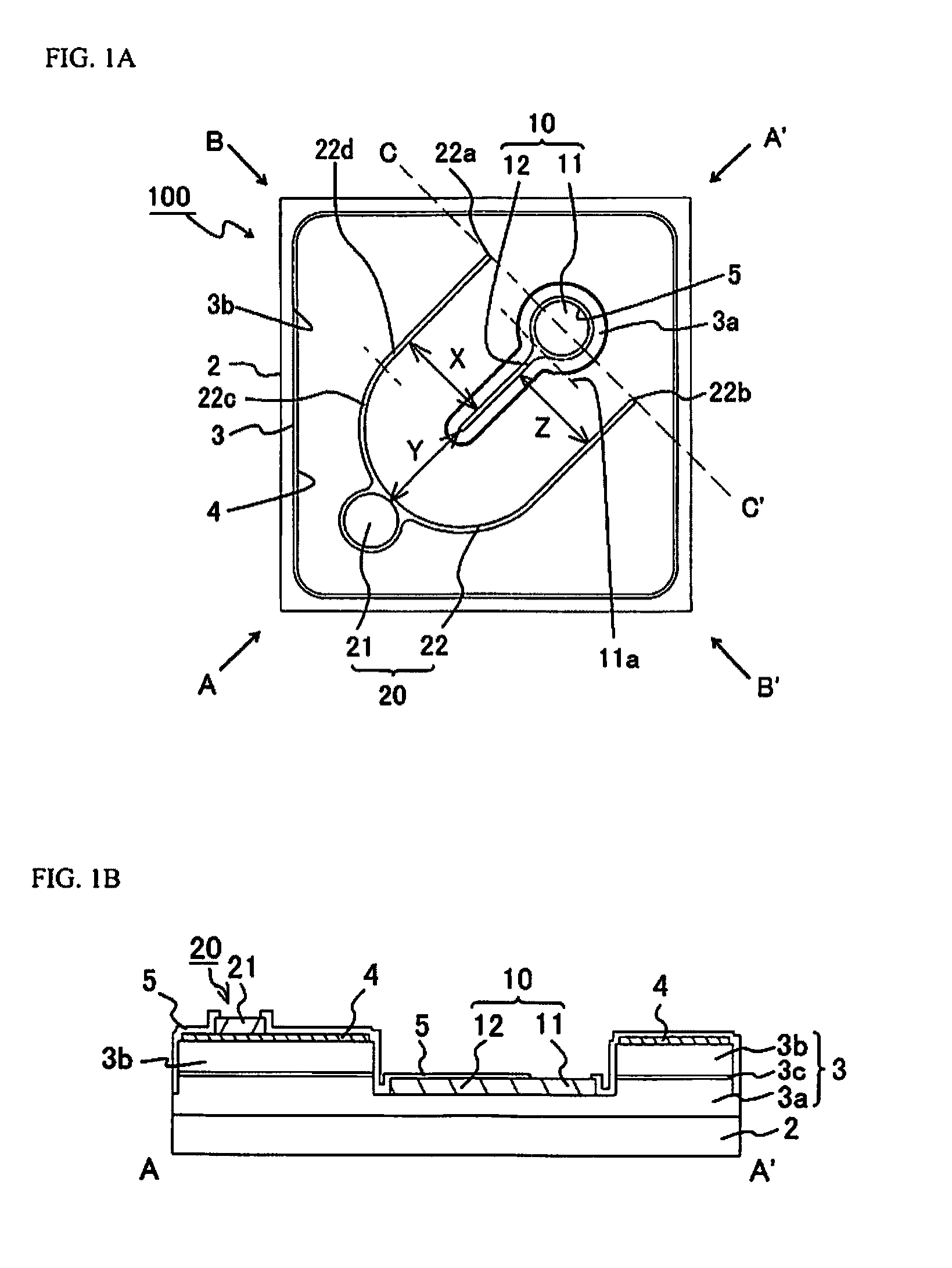
[0072]A light emitting element 100 according to Embodiment 1 includes, as shown in FIG. 1A and FIG. 1B, a substrate 2, a semiconductor layer 3 arranged on the substrate 2, a first electrode 10 disposed on the semiconductor layer 3, and a second electrode 20 arranged over the semiconductor layer 3 and outer periphery of the first electrode 10.

[0073]The semiconductor layer 3 includes a first conductivity-type semiconductor layer 3a (for example, an n-layer), an active layer 3c, and a second conductivity-type semiconductor layer 3b (for example, a p-layer).

[0074]The substrate 2 and the semiconductor layer 3 (particularly, the second conductivity-type semiconductor layer 3b) has an approximately square shape in a plan view. For example, the length of a side of the substrate2 is 460 μm.

[0075]The first electrode 10 is disposed on the first conductivity-type semiconductor layer 3a which is exposed by removing a part of the second conductivity-type semiconductor layer 3b and the active laye...

example 1 of embodiment 1

Variant Example 1 of Embodiment 1

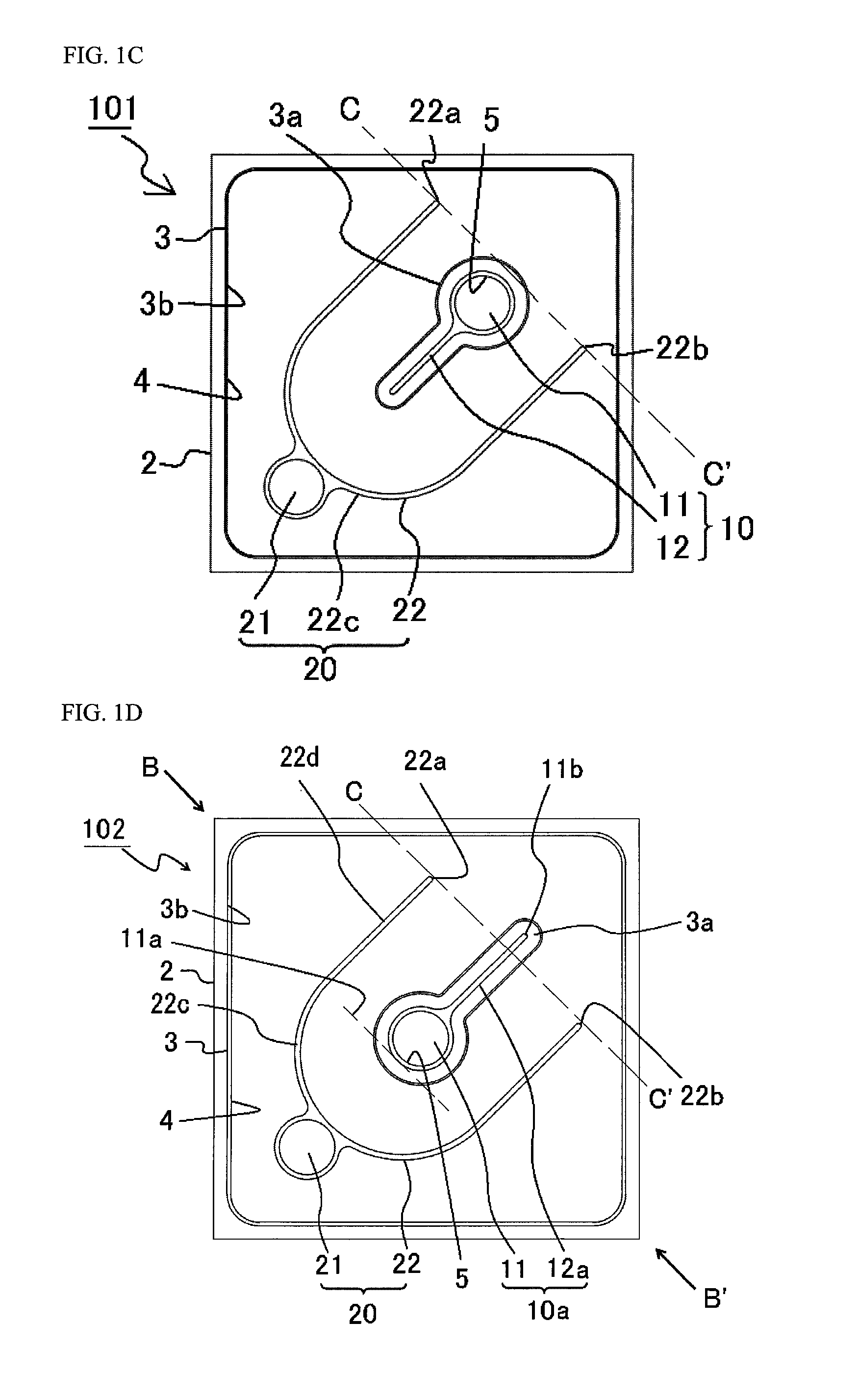
[0082]Also, as shown in FIG. 1C, a light emitting element 101 has a substantially similar structure as the light emitting element 100, as the light emitting element 101 includes a substrate 2, a semiconductor layer 3 disposed on the substrate 2, a first electrode 10 disposed on the semiconductor layer 3, and a second electrode 20 arranged over the semiconductor layer 3 and at outer periphery of the first electrode 10.

[0083]Also, the entire of the first connecting portion 11 is disposed closer side to the second connecting portion 21 than the a straight line C-C′ intersecting the two tip portions 22a and 22b of the second portions 22d of the respective second extending portions 22. As shown in FIG. 1C, the straight line C-C′ is spaced apart from the first electrode 10. With this arrangement, the distance between the first connecting portion 11 and the second connecting portion 21 can be reduced, so that resistance between the first connecting portion ...

example 2 of embodiment 1

Variant Example 2 of Embodiment 1

[0084]Also, as shown in FIG. 1D, a light emitting element 102 has a substantially similar structure as the light emitting element 100, as the light emitting element 102 includes a substrate 2, a semiconductor layer 3 disposed on the substrate 2, a first electrode 10a disposed on the semiconductor layer 3, and a second electrode 20 arranged over the semiconductor layer 3 and at outer periphery of the first electrode 10a.

[0085]The first electrode 10a includes a first connecting portion 11 and a first auxiliary extending portion 12a extending from the first connecting portion 11.

[0086]The first connecting portion 11 is arranged on the second diagonal line B-B′ and the center portion of the first connecting portion 11 is on the second diagonal line B-B′. Thus, the first connecting portion 11 is arranged so that the end portion 11a of the first connecting portion 11 which is close to the second connecting portion 21 is closer side to the second connectin...


PUM


Abstract

A light emitting element includes a first conductivity-type semiconductor layer, a first electrode, a second conductivity-type semiconductor layer and a second electrode. The second conductivity-type semiconductor layer has a square peripheral shape. The first electrode includes a first connecting portion on a first diagonal line and a first extending portion extending from the first connecting portion onto the first diagonal line. The second electrode includes a second connecting portion on the first diagonal line facing the first connecting portion via the first extending portion. Two second extending portions extend from the second connecting portion and having a first portion and a second portion respectively. The first connecting portion includes an end portion closer to the second connecting portion than a straight line intersecting the tip ends of the two second extending portions, and a center portion at a side father from the second connecting portion than the second diagonal line.

Description

CROSS-REFERENCE TO RELATED APPLICATION[0001]This application claims priority to Japanese Patent Applications No. 2012-288664, filed on Dec. 28, 2012 and No. 2013-220976, filed on Oct. 24, 2013. The entire disclosure of Japanese Patent Applications No. 2012-288664 and No. 2013-220976 are hereby incorporated herein by reference.BACKGROUND OF THE INVENTION[0002]1. Technical Field[0003]The present invention relates to a light emitting element, and particularly to an electrode structure of the light emitting element.[0004]2. Background Art[0005]There have been various developments in the art to obtain uniform emissions from a light emitting element. For example, for a light emitting element having a quadrilateral outer shape, electrode structures in which either a second electrode or a first electrode is disposed at a center portion of an upper surface of a light emitting element, and the other electrode is disposed embracing it (see Patent Literature 1: JP 2011-61077 A, Patent Literatur...

Claims


Application Information

Patent Timeline
Patent Type & Authority Patents(United States)
IPC IPC(8): H01L27/088H01L33/38H01L33/36H01L33/20
CPCH01L33/36H01L33/38H01L33/20H01L2924/0002H01L2924/00
Inventor SATO, KOSUKE
Owner NICHIA CORP
Why Eureka
Try Eureka