Endoscopic observation support system

a technology for supporting systems and endoscopes, which is applied in the field of supporting endoscopes, can solve the problems of difficult to conduct endoscope surgery with a very limited field of view, difficult to continue endoscope surgery, and doctors require a lot of skill to conduct endoscope surgery, etc., to achieve convenient user recognition, prevent misoperation, and reliably recognize positional relationships

Active Publication Date: 2016-06-28
FUJIFILM CORP
View PDF36 Cites 9 Cited by
  • Summary
  • Abstract
  • Description
  • Claims
  • Application Information

AI Technical Summary

Benefits of technology

[0014]An aspect of an endoscopic observation support program of the invention causes a computer to carry out the steps of: obtaining a 3D medical image representing an interior of a body cavity of a subject; identifying a position of a (first) structure of interest in the body cavity in the 3D medical image; obtaining a real-time position and a real-time posture of an endoscope inserted in the body cavity detected by position and posture detecting means; obtaining information of an angle of view of the endoscope; determining a virtual field of view of a virtual endoscope positioned at an endoscope-corresponding position, the endoscope-corresponding position being a position in the 3D medical image corresponding to the detected position of the endoscope, based on the identified position of the (first) structure of interest, the detected position and posture of the endoscope in the 3D medical image, and the angle of view of the endoscope, such that the position of the (first) structure of interest is contained within the virtual field of view and the virtual field of view has continuity with an endoscope-corresponding field of view, the endoscope-corresponding field of view being a field of view of the 3D medical image corresponding to a field of view of the endoscope; generating, from the 3D medical image inputted, a virtual endoscopic image having the virtual field of view with a view point thereof being the endoscope-corresponding position; and causing display means to display the virtual endoscopic image.
[0017]In a case where the generation of the virtual endoscopic image is repeated in response to detection of the position and posture of the endoscope, real-time update of both the real endoscopic image and the virtual endoscopic image along with movement of the endoscope is achieved.
[0027]According to the invention, from an inputted 3D medical image, which shows the interior of a body cavity of a subject, a virtual endoscopic image is generated and displayed, where the view point of the virtual endoscopic image is a position in the 3D medical image corresponding to a position of an endoscope detected by position and posture detecting means, the field of view of the virtual endoscopic image contains a position of the structure of interest, and the field of view of the virtual endoscopic image has continuity with the field of view of the endoscope. The field of view of the displayed virtual endoscopic image is determined such that the position of the structure of interest is always contained in the field of view, thereby allowing the user to reliably recognize the positional relationship and the approach between the endoscope and the structure of interest, and helping to prevent misoperation, etc., during surgery or examination. Further, the field of view of the virtual endoscopic image has continuity with the field of view of the endoscope. This facilitates the user to recognize the positional relationship between these fields of view. For example, even when the structure of interest is not contained in the real endoscopic image, the user can easily recognize how the endoscope should be moved to make the structure of interest be contained in the field of view of the real endoscope, and this improves operability of the endoscope during surgery.
[0028]Further, at this time, the view point and the field of view of the virtual endoscope of the continuously displayed virtual endoscopic image are changed real-time by feedback of the detected real-time position of the endoscope. This allows the user to dynamically and more appropriately recognize the approach of the endoscope to the structure of interest.
[0029]Still further, in the case where the real endoscopic image representing the interior of the body cavity is formed by real-time imaging with the endoscope, and the virtual endoscopic image and the real endoscopic image which is formed almost at the same time when the position and posture of the endoscope used to generate the virtual endoscopic image are detected are displayed with being superimposed one on the other and corresponding positions between the virtual endoscopic image and the real endoscopic image being aligned with each other, the displayed real endoscopic image and virtual endoscopic image show the state of the interior of the body cavity almost at the same point of time, and thus the real endoscopic image and the virtual endoscopic image are continuously displayed in a temporally synchronized manner. Yet further, in the case where the generation of the virtual endoscopic image is repeated in response to detection of the position of the endoscope, real-time update of both the real endoscopic image and the virtual endoscopic image is achieved. That is, the field of view of the real endoscopic image changes along with movement or rotation of the endoscope, and the field of view of the virtual endoscopic image changes along with movement, etc., of the endoscope. In this manner, the user can observe the interior of the body cavity with complementary using the real endoscopic image and the virtual endoscopic image.

Problems solved by technology

However, conducting surgery with a very limited field of view of the endoscope is highly difficult, and doctors require a lot of skill to conduct the endoscopic surgery.
If a blood vessel or an organ of the patient is damaged by mistake and breeds during the endoscopic surgery, it is impossible to continue the endoscopic surgery and the doctor has to conduct conventional surgery involving laparotomy, thoracotomy, or the like.
Therefore, depending on the positional relationship between the endoscope and a site of interest, such as a surgical tool or a site of surgical interest, the site of interest may not sometimes be shown in the virtual endoscopic image and the real endoscopic image, and the doctor cannot recognize the approach of the endoscope to the site of interest in such a case.

Method used


Image

  • Endoscopic observation support system
  • Endoscopic observation support system
  • Endoscopic observation support system

Examples


first embodiment

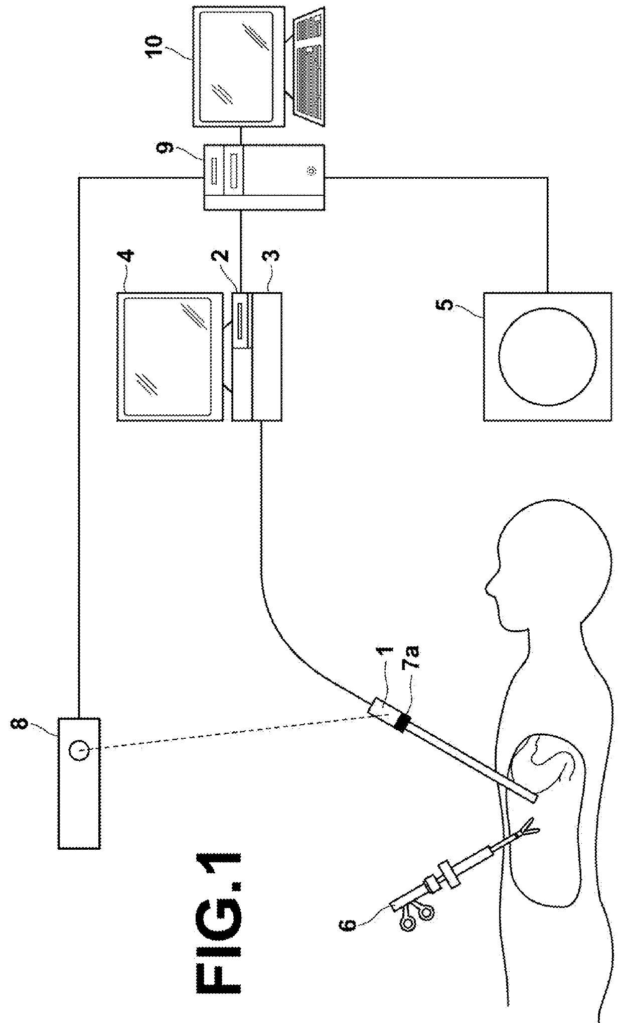
[0061]FIG. 1 is a hardware configuration diagram illustrating the outline of the endoscopic observation support system according to the invention. As shown in the drawing, the system includes an endoscope 1, a digital processor 2, a light source device 3, a real endoscopic image display 4, a modality 5, a surgical tool 6, an endoscope marker 7a, a position sensor 8, an image processing workstation 9, and an image processing workstation display (which will hereinafter be referred to as “WS display”) 10.

[0062]In this embodiment, the endoscope 1 is a hard endoscope for the abdominal cavity, and is inserted in the abdominal cavity of a subject. Light from the light source device 3 is guided by an optical fiber and emitted from the tip portion of the endoscope 1, and an image of the interior of the abdominal cavity of the subject is taken by an imaging optical system of the endoscope 1. The digital processor 2 converts an image signal obtained by the endoscope 1 into a digital image sign...

third embodiment

[0100]FIG. 9A schematically illustrates one example of the color template used in the invention. As shown in the drawing, this color template is defined such that the color of the virtual endoscopic image IVE is changed depending on a distance from the position PE of the endoscope 1 (which is the same as the view point position PVE of the virtual endoscope) to the surface of a structure in the abdominal cavity. For example, the virtual endoscopic image generating unit 27 detects a position where a change of pixel value along each line of sight of the perspective projection is larger than a predetermined threshold or a position where the pixel value is equal to or larger than a predetermined threshold as the surface of a structure in the abdominal cavity, and calculates the distance from the position PE of the endoscope 1 to the surface of the structure in the abdominal cavity. Then, the virtual endoscopic image generating unit 27 uses the color template to determine the pixel value ...

sixth embodiment

[0120]As described above, according to the invention, the virtual endoscopic image IVE which contains, in the field of view thereof, not only the position of structure of interest PI but also the surgical tool position PT is generated, thereby allowing the user to reliably recognize the relative positional relationship and the relative approach among not only the endoscope 1 and the structure of interest, but also the surgical tool 6.

[0121]Further, at this time, the field of view and the image content of the continuously displayed virtual endoscopic image IVE are changed real-time by feedback of the real-time position of the surgical tool 6 detected by the surgical tool position detecting unit 12. This allows the user to dynamically and more appropriately recognize the relative positional relationship and the relative approach among not only the endoscope 1 and the structure of interest, but also the surgical tool 6.

[0122]Further, the real endoscopic image forming unit 2 forms the r...


PUM


Abstract

A virtual field of view of a virtual endoscope, which is positioned at a position corresponding to a detected position of an endoscope in a 3D medical image, is determined based on a position of a structure of interest, the corresponding position and a posture of the endoscope, and an angle of view of the endoscope, such that the position of the structure of interest is contained within the virtual field of view and the virtual field of view has continuity with the field of view of the endoscope. From the 3D medical image inputted, a virtual endoscopic image having the determined virtual field of view with the view point thereof being the corresponding position of the endoscope is generated. The generated virtual endoscopic image is displayed on a WS display.

Description

BACKGROUND OF THE INVENTION[0001]1. Field of the Invention[0002]The present invention relates to a technology for supporting endoscopic observation during surgery or examination using an endoscope inserted in a body cavity of a subject, and in particular to a technology for supporting endoscopic observation using a virtual endoscopic image representing the interior of a body cavity of a subject.[0003]2. Description of the Related Art[0004]In recent years, surgery using an endoscope, such as laparoscopic surgery and thoracoscopic surgery, is drawing attention. The endoscopic surgery is advantageous in that it does not require laparotomy, thoracotomy, or the like, and only needs to make two or three holes of few centimeters in diameter for insertion of an endoscope and a surgical tool, thereby significantly reducing the burden imposed on the patient. However, conducting surgery with a very limited field of view of the endoscope is highly difficult, and doctors require a lot of skill t...

Claims


Application Information

Patent Timeline
Patent Type & Authority Patents(United States)
IPC IPC(8): A61B1/00A61B6/12A61B1/313A61B5/06A61B6/00A61B6/03
CPCA61B1/00055A61B1/0005A61B1/00009A61B1/3132A61B6/12A61B6/5211A61B5/064A61B6/032A61B6/466A61B6/486A61B2090/365A61B2034/2055A61B90/37G16H50/20A61B1/000094
Inventor KITAMURA, YOSHIRONAKAMURA, KEIGO
Owner FUJIFILM CORP
Why Eureka
Try Eureka