Liquid discharge apparatus and head unit

a liquid discharge apparatus and head unit technology, applied in the direction of electronic switching, pulse technique, printing, etc., can solve the problems of poor energy efficiency of the system, deterioration of the quality of printing, complication of the circuit, etc., and achieve the effect of preventing deterioration of print quality and simple configuration

Active Publication Date: 2016-06-28
SEIKO EPSON CORP
View PDF4 Cites 3 Cited by
  • Summary
  • Abstract
  • Description
  • Claims
  • Application Information

AI Technical Summary

Benefits of technology

[0009]An advantage of some aspects of the invention is to provide a technique which allows class D amplification of a source signal and preventing deterioration in print quality in a liquid discharge apparatus that performs class D amplification of a drive signal that is applied to a piezoelectric element, with a relatively simple configuration.
[0011]In this case, since no separate oscillation circuit is required, it is possible to prevent deterioration of print quality with a relatively simple configuration.
[0016]Meanwhile, when the frequency of the self-oscillation is higher than 8 MHz, resolution of the waveform of the drive signal becomes higher. However, an increase of a switching frequency in the transistor results in a great switching loss, and power-saving performance and heat saving performance better than in a linear amplification such as the class AB amplification or the like are lost.
[0019]In addition, in the liquid discharge apparatus, it is preferable that a self-resonant frequency of the capacitor is higher than a frequency of the self-oscillation. In this manner, when the self-resonant frequency of the capacitor is higher than the frequency of the self-oscillation, it is possible to prevent occurrence of abnormal oscillation, a variation in the frequency of the self-oscillation, or the like.
[0020]In the liquid discharge apparatus, it is preferable that a self-resonant frequency of the capacitor is 1.5 or more times a frequency of the self-oscillation. In this manner, when the self-resonant frequency of the capacitor is 1.5 or more times the frequency of the self-oscillation, it is possible to prevent occurrence of abnormal oscillation, a variation in the frequency of the self-oscillation, or the like.

Problems solved by technology

However, since the system is poor in energy efficiency, class D amplification has been proposed recently (see JPA-2010-114711).
Incidentally, in the configuration in which the PLL is provided in the feedback path (loop) of the self-oscillation, an oscillation circuit for generating the reference signal is separately required, which results in complication of the circuit.
When the waveform of the drive signal has the blunt edge, the piezoelectric element which operates in accordance with a rising or falling edge of the waveform is gradually displaced and tailing or discharge failure during discharge occurs such that quality of the printing deteriorates.
However, an increase of a switching frequency in the transistor results in a great switching loss, and power-saving performance and heat saving performance better than in a linear amplification such as the class AB amplification or the like are lost.

Method used


Image

  • Liquid discharge apparatus and head unit
  • Liquid discharge apparatus and head unit
  • Liquid discharge apparatus and head unit

Examples


Embodiment Construction

[0047]Hereinafter, embodiments of the invention will be described with reference to the drawings.

[0048]A printing apparatus according to the embodiment is an ink jet printer, that is, a liquid discharge apparatus, which discharges an ink in accordance with image data supplied from an external host computer such that an ink dot group is formed on a printing medium such as paper, and thereby prints an image (including a text, a figure, or the like) in accordance with the image data.

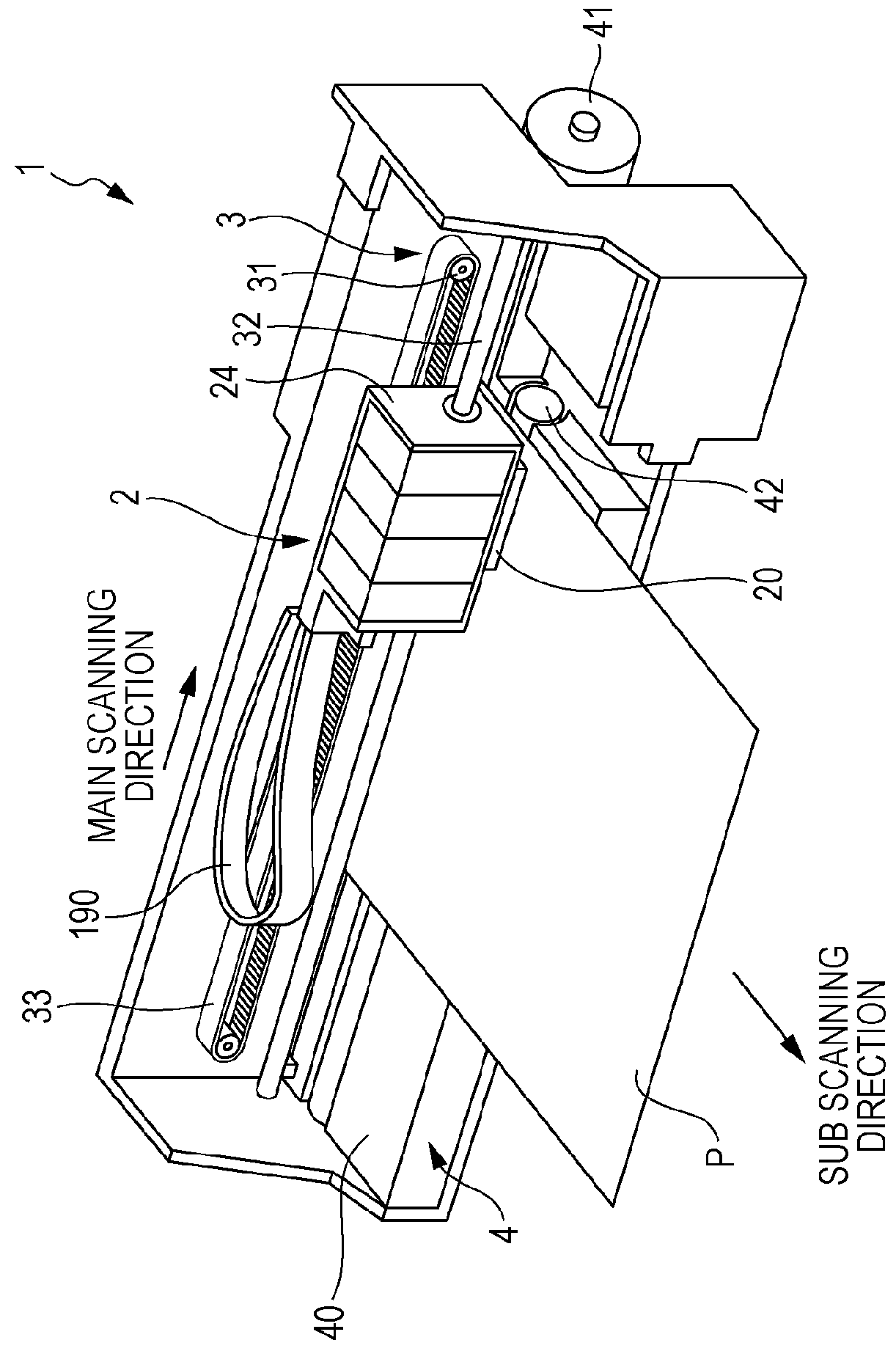
[0049]FIG. 1 is a perspective view schematically illustrating an internal configuration of a printing apparatus.

[0050]As illustrated in FIG. 1, the printing apparatus 1 includes a traveling mechanism 3 that causes a traveling body 2 to travel (reciprocate) in a main scanning direction.

[0051]The traveling mechanism 3 has a carriage motor 31 that is a drive source of the traveling body 2, a carriage guide shaft 32 having both ends which are fixed, and a timing belt 33 that extends to be substantially parallel...


PUM


Abstract

A liquid discharge apparatus includes: a modulation circuit that generates a modulated signal by pulse-modulating a source signal through self-oscillation; a pair of transistors that include a high-side transistor and a low-side transistor and amplify the modulated signal to generate an amplified modulated signal; a low-pass filter that includes an inductor and a capacitor and smoothes the amplified modulated signal to generate a drive signal; a piezoelectric element that is displaced by application of the drive signal thereto; a cavity that is filled with a liquid inside and has an internal volume which changes when the piezoelectric element is displaced; and a nozzle that is provided to discharge the liquid inside the cavity in response to the change of the internal volume of the cavity. A shortest distance between the low-side transistor and the capacitor is shorter than a shortest distance between the high-side transistor and the capacitor.

Description

[0001]The entire disclosure of Japanese Patent Application No. 2014-164131, filed Aug. 12, 2014 is expressly incorporated by reference herein.BACKGROUND[0002]1. Technical Field[0003]The present invention relates to a liquid discharge apparatus and a head unit.[0004]2. Related Art[0005]As an ink jet printer that discharges an ink and prints an image or a document, a printer that uses piezoelectric elements (for example, piezo elements) is known. The piezoelectric elements are provided respectively corresponding to a plurality of nozzles in a head unit and are respectively driven in response to drive signals and thereby, a predetermined amount of an ink (liquid) is discharged from the nozzle at a predetermined timing such that a dot is formed. The piezoelectric element is a capacitive load like a capacitor in terms of electric power. Therefore, a sufficient current supply is required to operate the piezoelectric elements of the nozzles.[0006]Therefore, a configuration is employed, in ...

Claims


Application Information

Patent Timeline
Patent Type & Authority Patents(United States)
IPC IPC(8): B41J29/38B41J2/045
CPCB41J2/04541B41J2/04581B41J2/0455B41J2202/11H03K17/687
Inventor TAKAGI, TETSUOUEMATSU, HIDEKAZU
Owner SEIKO EPSON CORP
Why Eureka
Try Eureka