Transflective liquid-crystal display

Active Publication Date: 2016-07-05
INNOLUX CORP
View PDF1 Cites 0 Cited by
  • Summary
  • Abstract
  • Description
  • Claims
  • Application Information

AI Technical Summary

Benefits of technology

[0008]In one embodiment of the invention, there is no cell gap modification layer disposed on the transparent electrode in the reflective area. In one embodiment, there is no electrode disposed on the second substrate in the first and second sub-regions, and a plurality of liquid-crystal molecules of the liquid-crystal layer in the first and second sub-regions is arranged by a fringe electric field of the pixel electrode. Utilizing the embodiment of the invention, there is no cell gap modification layer, the arrangement of the liquid-crystal molecules are not influenced by the cell gap modification laye

Problems solved by technology

However, the cell gap modification layer increases the cost of the transflective liquid-crystal display.
Additionally, the edge of the cell gap modification layer influences the arrangement of the li

Method used


Image

  • Transflective liquid-crystal display
  • Transflective liquid-crystal display
  • Transflective liquid-crystal display

Examples


Example

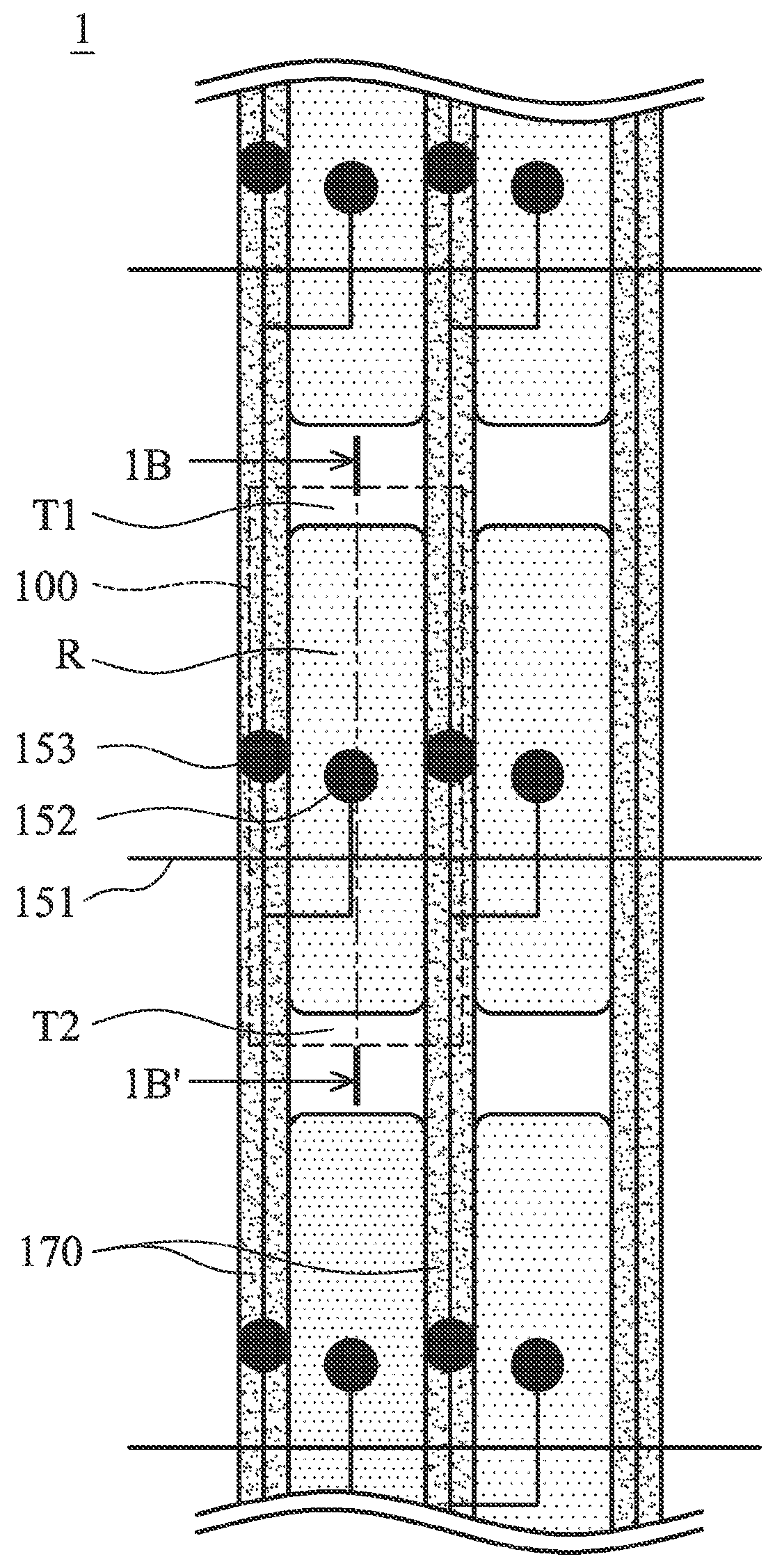
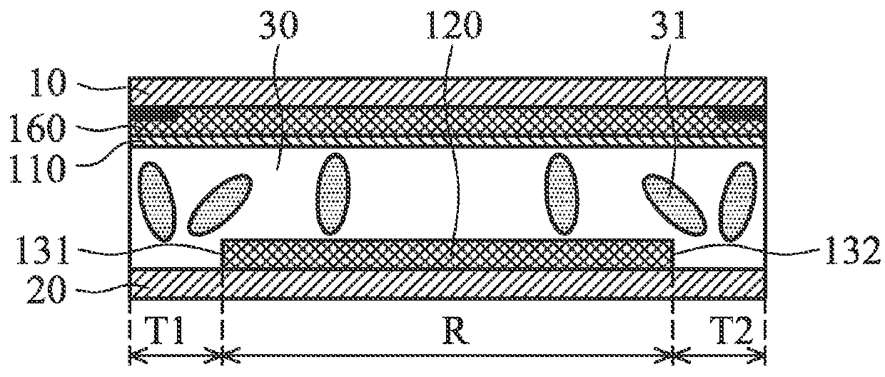
[0020]FIGS. 1A and 1B show a transflective liquid-crystal display 1 of a first embodiment of the invention. The transflective liquid-crystal display 1 comprises a liquid-crystal layer 30, a first substrate 10 and a second substrate 20. The liquid-crystal layer 30 is sandwiched between the first substrate 10 and the second substrate 20, to define an array of pixels 100 on the second substrate 20. Each pixel 100 comprises a reflective area R, a transmissive area, a transparent electrode (common electrode) 110 and a pixel electrode 120. The reflective area surrounds the transmissive area

[0021]The transmissive area includes two sub-region (first sub-region T1 and second sub-region T2) arranged in two opposite side of the reflective area pixel electrode. The reflective area R comprises a first side 131 and a second side 132. The first sub-region T1 is adjacent to the first side 131 of the reflective area R. The second sub-region T2 is adjacent to the second side 132 of the reflective are...

Example

[0029]FIGS. 4A and 4B shows a transflective liquid-crystal display of a second embodiment of the invention, comprising a liquid-crystal layer 30, a first substrate 10 and a second substrate 20. The liquid-crystal layer 20 is sandwiched between the first substrate 10 and the second substrate 20, to define an array of pixels 100′ in the liquid-crystal layer 20. Each pixel 100′ comprises a transmissive area T, a reflective area R, a transparent electrode (common electrode) 110 and a pixel electrode 120′. The transmissive area T comprises a first side 131′ and a second side 132′. The reflective area R is adjacent to the first side 131′ of the transmissive area T. The transparent electrode 110 is disposed on the first substrate 10. The pixel electrode 120′ is disposed on the second substrate 20 in the transmissive area T. In the second embodiment, a reflector 180 is disposed on the second substrate 20 in the reflective area R. The reflector 180 is floating or connected to common voltage....


PUM


Abstract

A transflective liquid-crystal display is provided, including a liquid-crystal layer, a first substrate and a second substrate. The liquid-crystal layer is sandwiched between the first and second substrates to define an array of pixels on the second substrate. Each pixel includes a reflective area, a transmissive area and a pixel electrode. The transmissive area is adjacent to the reflective area. The pixel electrode is disposed on the second substrate and electrical connecting to a data line, wherein the pixel electrode is only formed reflective electrode in the reflective area and has reflectivity.

Description

BACKGROUND OF THE INVENTION[0001]1. Field of the Invention[0002]The present invention relates to a liquid-crystal display, and in particular to a transflective liquid-crystal display.[0003]2. Description of the Related Art[0004]According to different designs of light sources, liquid-crystal display panels may be divided into three categories: transmissive liquid-crystal display panels, reflective liquid-crystal display panels, and transflective liquid-crystal display panels. Combining the advantages of the transmissive liquid-crystal display panel and the reflective liquid-crystal display panel, the display quality of the transflective liquid-crystal display panel may be ensured in indoor environments as well as outdoor environments with strong ambient light.[0005]In a conventional transflective liquid-crystal display, a cell gap modification layer is disposed on an upper transparent layer in a reflective area thereof to adjust a cell gap of the reflective area. The cell gap of the ...

Claims


Application Information

Patent Timeline
IPC IPC(8): G02F1/1335G02F1/1343G02F1/1337
CPCG02F1/133555G02F1/13439G02F1/133512G02F1/133514G02F1/133707G02F1/133553G02F1/136227G02F1/134318
Inventor SHIBAZAKI, MINORU
Owner INNOLUX CORP
Why Eureka
Try Eureka