
Toilet seat lifter and rotary spring-loaded actuator

a technology of rotary springs and actuators, which is applied in the direction of fluid pressure actuators, gearing, domestic applications, etc., can solve the problems of affecting the use of toilet seats, and often damaged by users in public conveniences, so as to prevent the free fall of the cover, the effect of lifting and lowering the toilet seat and wide utilisation of the toilet sea

Inactive Publication Date: 2016-07-12
ZBIGNIEW KORZELSKI - DELKI POLPOINT
View PDF6 Cites 0 Cited by
  • Summary
  • Abstract
  • Description
  • Claims
  • Application Information

AI Technical Summary

Benefits of technology

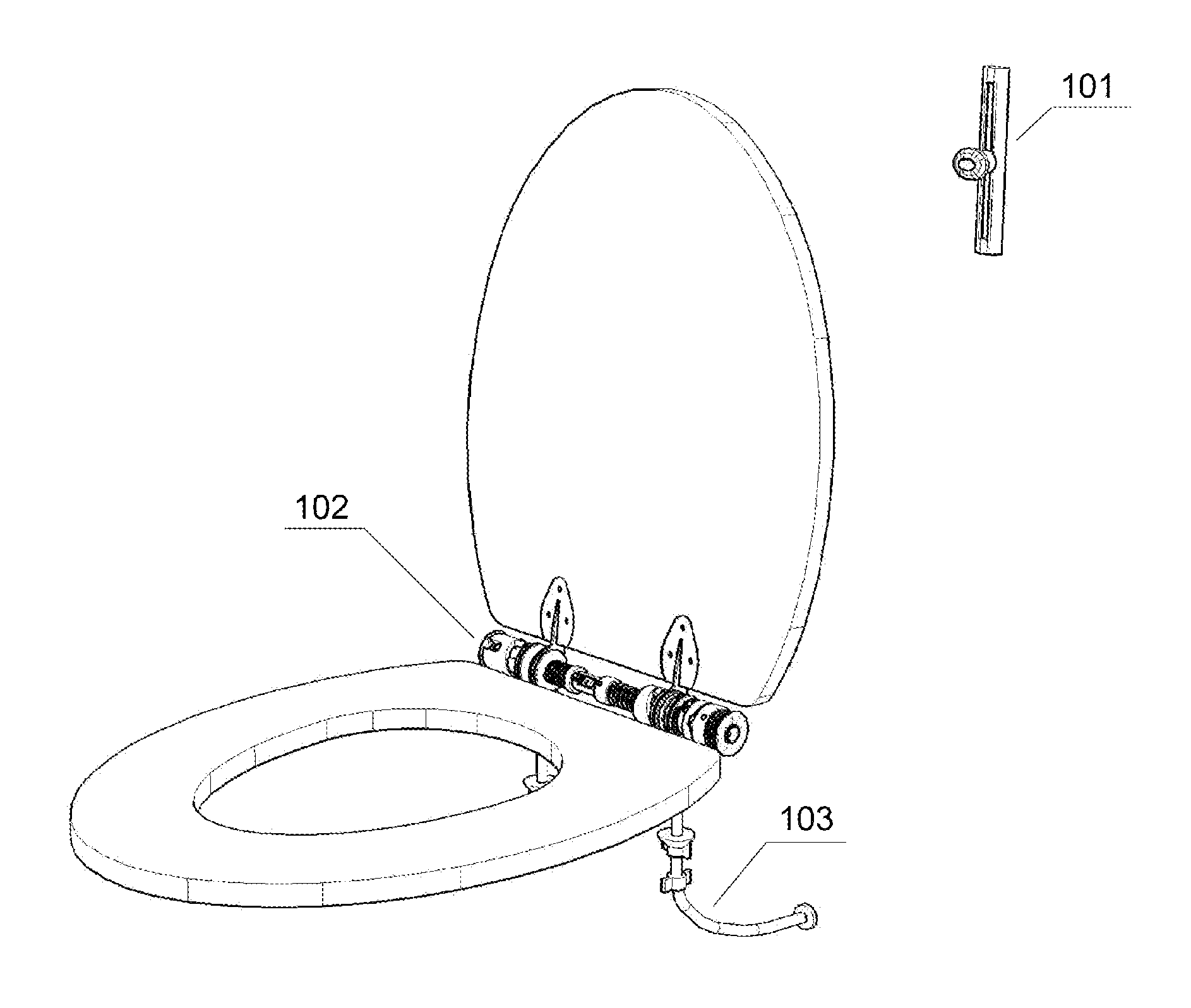
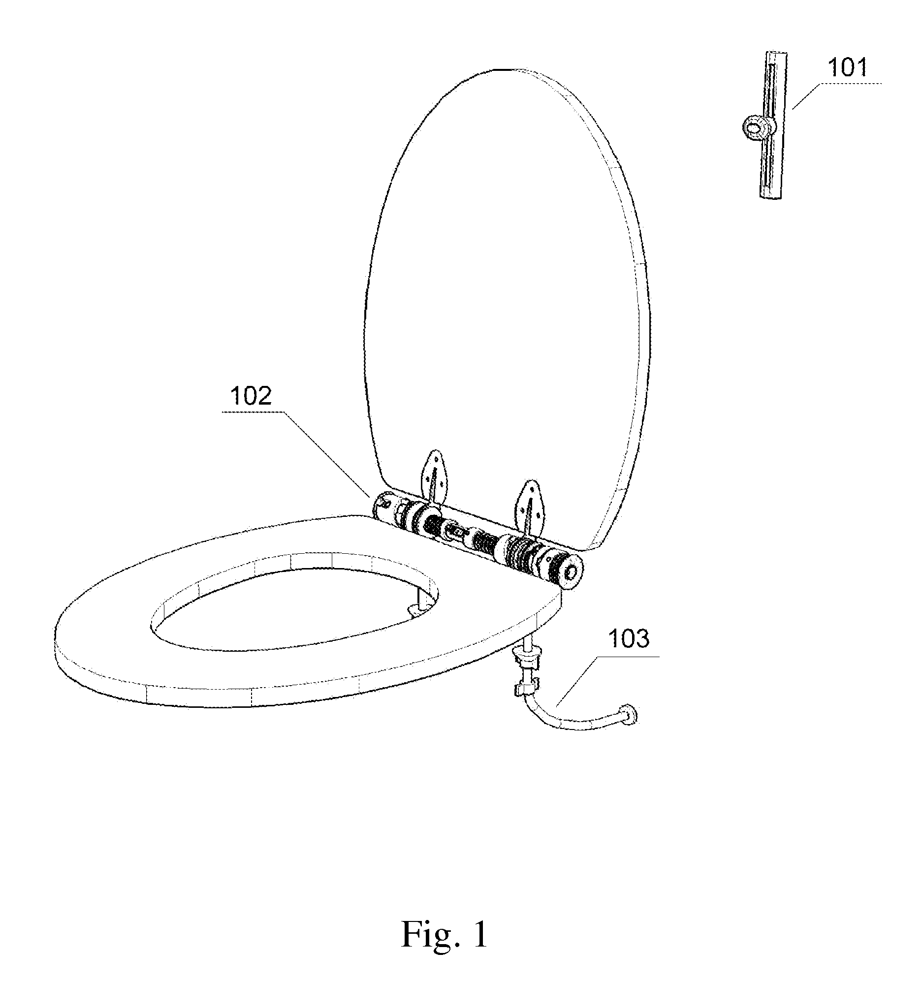
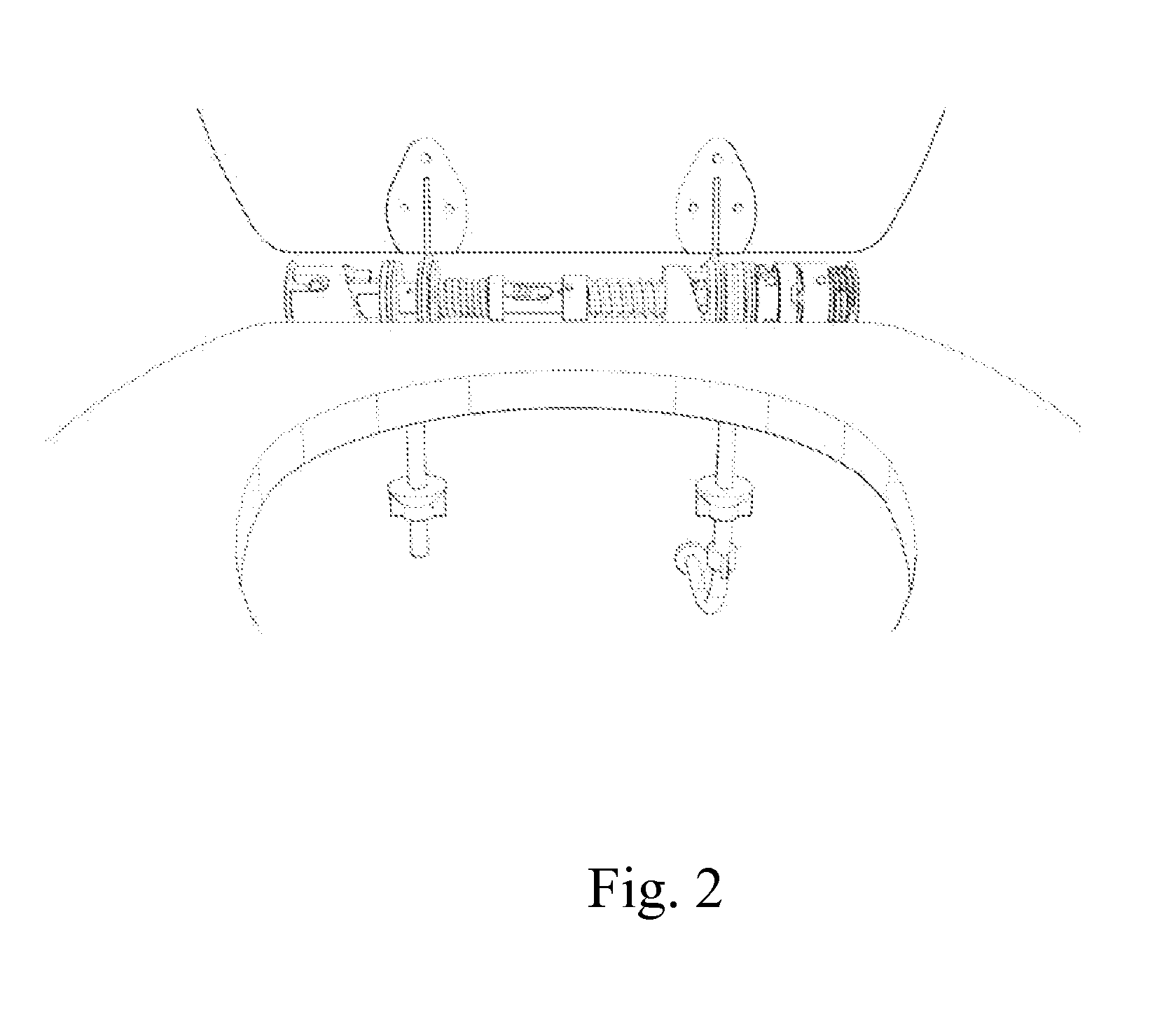
[0019]The structural pipe of the lifter has several mounting openings and cut-outs of various shapes. The mating modules—the left reciprocating one and the left rotary one are mounted on the structural pipe on the left side of the lifter. The left reciprocating module to the left lifter spring connecting member is located inside the structural pipe from its left side. This connecting member is coupled to the left reciprocating module by means of a mounting peg. This peg passes through an adequately shaped cut-out in the structural pipe, enabling its free reciprocating motion. The internal connecting member is coupled on the other side to the sleeve of the lifter left spring through a peg passing by the adequately shaped cut-out in the structural pipe.
[0106]The advantage of a rotary spring-loaded actuator as invented is its simple construction, operational reliability, and versatility of utilisation especially in applications in which other type actuators have low effectiveness or are impossible to use. The rotary spring-loaded actuator features significant constructional possibilities of using modules interaction relationship on state of spring tension or spring pressure force influence on the operation of the modules. It is possible to combine the actuators in series or in groups. The rotary spring-loaded actuator finds wide application in interaction with other equipment, in which it may be used as a subassembly or constitute itself as the main structural component.

Problems solved by technology

External cables render the use of the toilet bowl difficult for its user.
Furthermore, they are frequently damaged in public conveniences by their users.
The disadvantage of this device is the necessity of fastening an additional tray for the mounting of the device, as well as the necessity of using a toilet seat of special design and adequately bent up rear parts of the seat and cover.
The disadvantage of this invention is the high risk of damaging the toilet seat lifting gear by malicious users, as well as the possibility of lifting only and exclusively the toilet seat.
Obtaining of rotary motion in all known solutions of actuators operating in reciprocating mode is either impossible, or accomplished by means of very complex and costly, additional hydraulic-mechanical equipment.
This structure significantly reduces the friction resistance existing within the contact of the modules during the operation of the lifter.
Continued rotary motion of the latches control sleeve transfers the rotary sleeve rotary motion through engaged latches onto the right seat hinge, which results in the lifting of the toilet seat.
The rotary module position change results in a relative shift of the reciprocating module, which causes the tensioning or releasing of the spring.
This structure significantly reduces the friction resistance existing within the contact of the modules during the operation of the rotary spring-loaded actuator.
This structure significantly reduces the friction resistance existing within the contact of the modules during the operation of rotary spring-loaded actuator.
Such a solution enables its utilisation in public conveniences, which are most seriously endangered with the unpredictable actions of users.

Method used


Image

  • Toilet seat lifter and rotary spring-loaded actuator
  • Toilet seat lifter and rotary spring-loaded actuator
  • Toilet seat lifter and rotary spring-loaded actuator

Examples


Embodiment Construction

[0138]The 1.1 structural pipe is seated in G openings of 2a and 2b mounting lugs 201 and 202 holders. The 1.1 structural pipe features C1 lengthwise opening for the seating of 16.1 mandrel limiting reciprocating motion of 14.2 module, C2 opening of 16.2 mandrel connecting 14.2 module with 16.6 spring through 16.3 internal connecting member, C3 opening enabling the reciprocating connection of 16.3 internal connecting member with a 16.5 sleeve, C4 openings fastening 13.2 thrust sleeve of 13.3 spring through 13.1 mandrel, C5 opening of 8.7 peg rotation, C6 opening of 8.4 peg rotation, as well as the C7 opening for the seating of the 8.2 mandrel that protects 8.1 disconnecting sleeve against performing of rotary motion. The 16.6 and 13.3 springs with 16.5 and 13.2 rings are seated between 2a and 2b mounting lugs on the 1.1 structural pipe. The 16.6 spring presses on 15.1 spacer sleeve with 3a left cover hinge seated. The 13.3 compression spring presses through 11.1 right reciprocating m...


PUM


Abstract

A toilet seat lifter is mounted together with a toilet seat on a toilet bowl. The design of the lifter enables the lifting and lowering of a toilet cover and / or toilet seat by means of a lifter controlling device or in the traditional manner. During the lifting of the toilet seat, the gear of the device assists the lifting of its components while, in the case of lowering them, the gear prevents their inert from falling. The design of the lifter enables the positioning of the toilet seat in a lifted position, preventing their resting against the wall or toilet cistern. In case of improper use, consisting in the lifting of the toilet seat components by means of a controlling device and simultaneously lowering them in the traditional manner (or inversely), the disconnection of the gear will result, precluding its damage.

Description

BACKGROUND[0001]1. Field[0002]The aspects of the disclosed embodiments relate to a toilet seat lifter with a rotary spring-loaded actuator. The rotary spring-loaded actuator mounted in the toilet seat lifter represents essential gear of the cover and toilet seat lifting equipment. The lifting and lowering of the toilet seat with the lifter is performed without the direct contact of toilet user's hand with the cover or seat of the toilet. The toilet seat lifter is mounted together with the toilet seat on the toilet bowl.[0003]Particular areas of the invention's utilisation are generally available public conveniences: in office buildings, hotels, schools, hospitals, working places, etc.; toilets in public transport: railways, air and sea transport, as well as household toilets.[0004]2. Brief Description of Related Developments[0005]Known lifters of toilet seat are composed of a motor, which the rotary motion, through the mechanical structures of gear transmissions and catch pawls, is ...

Claims


Application Information

Patent Timeline
Patent Type & Authority Patents(United States)
IPC IPC(8): A47K13/10A47K13/12F16H21/44
CPCA47K13/10A47K13/12F16H21/44Y10T74/18888F15B15/06
Inventor KORZELSKI, ZBIGNIEW
Owner ZBIGNIEW KORZELSKI - DELKI POLPOINT
Learn More