
Combustion engine and method for operating a combustion engine with discharge of condensation water from the induction tract

Active Publication Date: 2016-07-19
AUDI AG
View PDF19 Cites 5 Cited by
  • Summary
  • Abstract
  • Description
  • Claims
  • Application Information

AI Technical Summary

Benefits of technology

The invention is about a method to prevent water hammer and damage to combustion engines caused by too much condensation water after cold starts or shutdowns. The method involves gradually and controlled supply of the condensation water to the combustion chamber through the charge air cooler, rather than discharging it all at once. This prevents excessive water hammer and allows for easier use of direct charge air coolers. The method also allows for adjustment and change of the partial volume flows through the charge air cooler and bypass, ensuring optimal engine performance with minimal impact on combustion.

Problems solved by technology

A problem is that under certain conditions the temperature of the charge air in the charge air cooler is lowered to the degree so as to result in an oversaturated state which may cause condensate or condensation water and / or even ice to form in the charge air cooler and / or in the induction tract which is downstream in the direction of flow of the charge air volume flow.
Even with the measures known from the state of the art, formation of condensation water and / or ice cannot be reliably avoided.
For example, condensation water can form in the charge air cooler and / or in the following induction tract during prolonged shutoff of the combustion engine, which can adversely affect the combustion process and / or can cause damage to the motor (water hammer).

Method used


Image

  • Combustion engine and method for operating a combustion engine with discharge of condensation water from the induction tract
  • Combustion engine and method for operating a combustion engine with discharge of condensation water from the induction tract
  • Combustion engine and method for operating a combustion engine with discharge of condensation water from the induction tract

Examples


Embodiment Construction

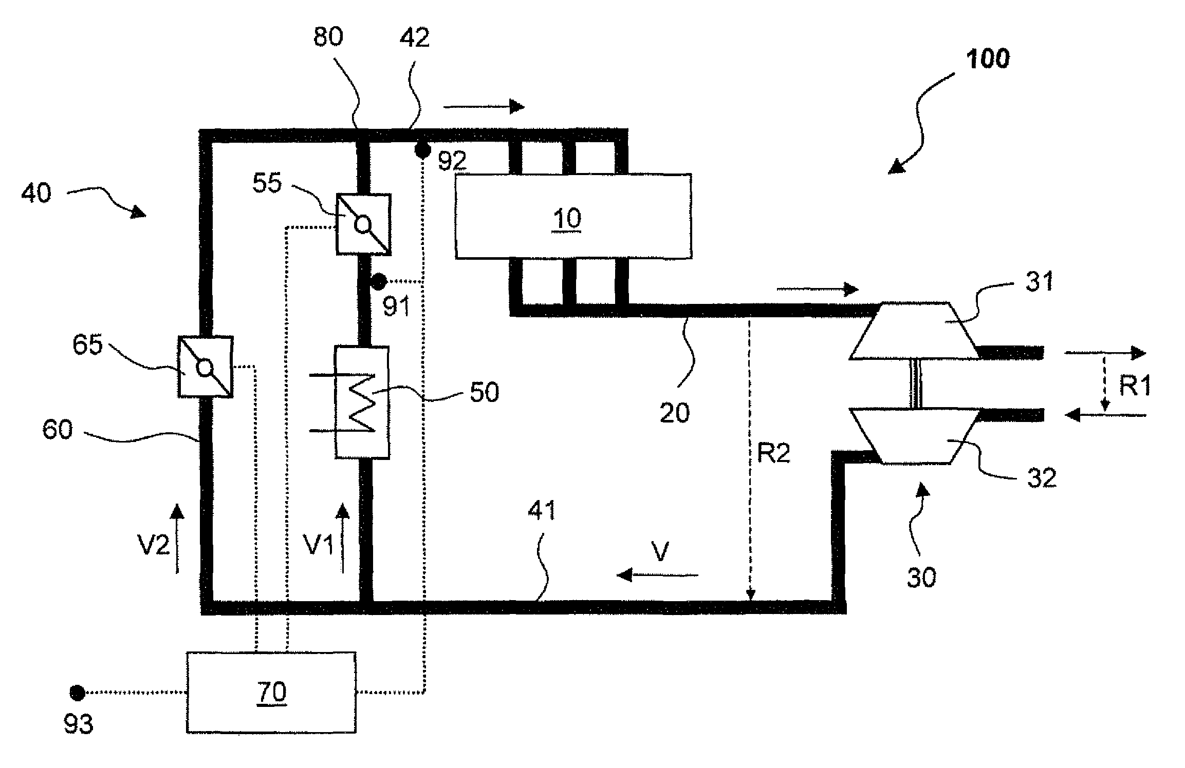
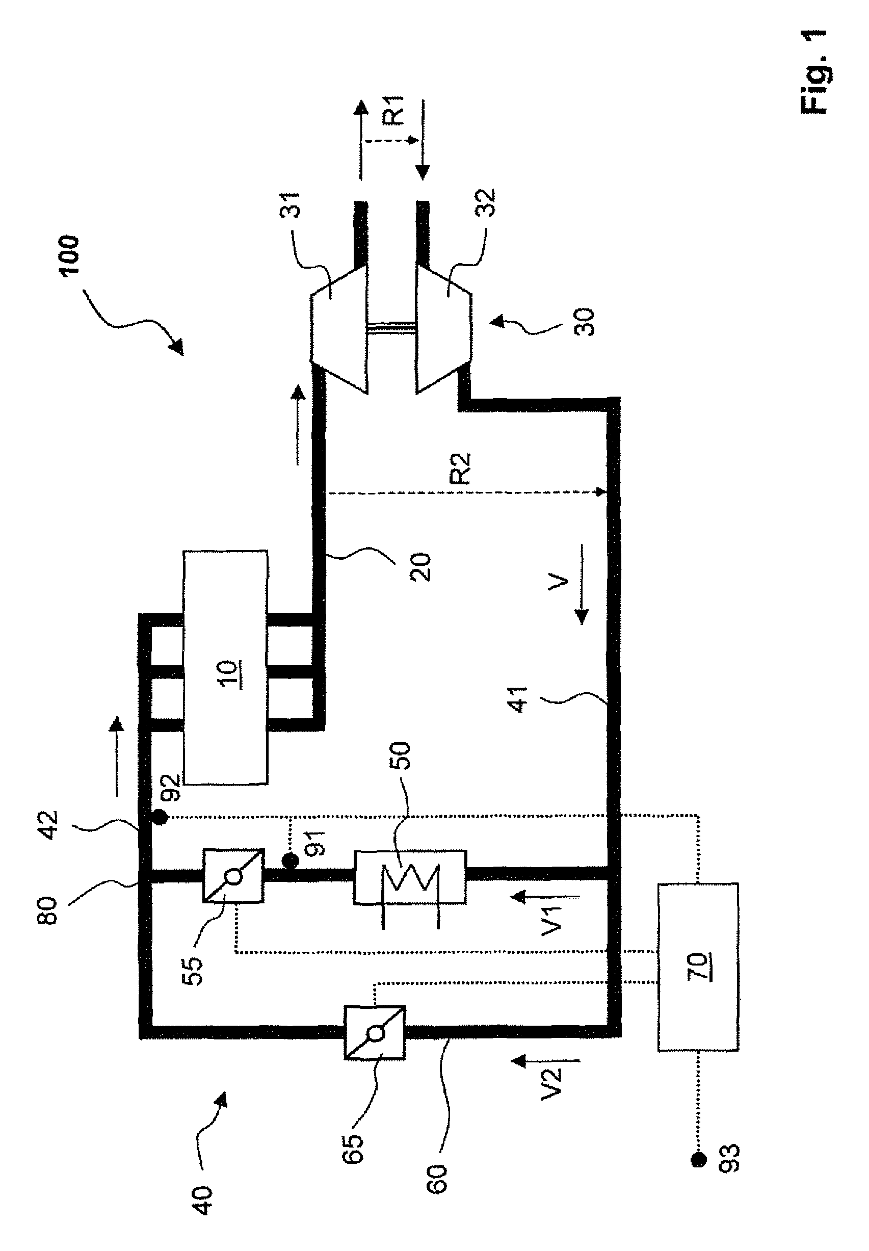
[0029]FIG. 1 shows a combustion engine 100, which has a combustion chamber 10 with multiple cylinders. In the exhaust duct 20, which leads away from the combustion chamber 10, a turbine 31 is located which belongs to a turbocharger 30 with a compressor 32. In the induction tract 40, which leads to the combustion chamber 10 is a charge air cooler 50 and a bypass 60 which is parallel to the charge air cooler 50. Via this induction tract 40, a charge air volume flow V is delivered to the combustion chamber 10 which volume flow is compressed by the compressor 32, wherein this can be fresh air or an exhaust gas-air mixture (fresh air with a proportion of re-circulated exhaust gas). The combustion engine 100 includes further an optional (switchable) exhaust gas recirculation R1 (low pressure exhaust gas re-circulation) and / or R2 (high pressure exhaust gas re-circulation). The section of the induction tract 40, which is located upstream of the charge air cooler 50, is designated with 41 an...


PUM


Abstract

A method for operating a combustion engine comprising charging and charge air cooling, wherein in a critical operating state the charge air volume flow through a charge air cooler is adjusted and / or temporally changed by means of at least one charge air cooler valve in such a manner that condensation water present in the charge air cooler and / or in the subsequent induction tract is fed only in harmless quantities successively into the combustion chamber and is thus discharged. The invention further relates to a combustion engine that can be operated according to the method.

Description

CROSS REFERENCES TO RELATED APPLICATIONS[0001]This application is the U.S. National Stage of International Application No. PCT / EP2012 / 001680, filed Apr. 19, 2012, which designated the United States and has been published as International Publication No. WO 2012 / 146357 and which claims the priority of German Patent Application, Serial No. 10 2011 018 958.0, filed Apr. 29, 2011, pursuant to 35 U.S.C. 119(a)-(d).BACKGROUND OF THE INVENTION[0002]The invention relates to a method for operating a combustion engine with charging and charge air cooling. The invention also relates to a combustion engine with at least one compressor and at least one charge air cooler downstream of the compressor.[0003]Charging or motor charging relates to the delivery of compressed charge air to the combustion chamber of a combustion engine in order to increase the performance and / or the efficiency of this combustion engine. The compression is usually accomplished by at least one supercharger which can be a t...

Claims


Application Information

Patent Timeline
IPC IPC(8): F02D41/00F02B29/04F02M35/10F02B37/00
CPCF02D41/0007F02B29/0418F02B29/0468F02B29/0493F02M35/1038F02B37/00Y02T10/146Y02T10/12
Inventor PFAB, CHRISTIAN
Owner AUDI AG
Learn More