Negative electrode active material including first, second, and third regions and power storage device including the negative electrode active material

a technology of active materials and negative electrodes, which is applied in the direction of electrolytic capacitors, cell components, electrochemical generators, etc., can solve the problems of promoting deterioration of power storage devices, and achieve excellent cycle characteristics, high charge and discharge efficiency, and high capacitance

Active Publication Date: 2018-07-17
SEMICON ENERGY LAB CO LTD
View PDF39 Cites 0 Cited by
  • Summary
  • Abstract
  • Description
  • Claims
  • Application Information

AI Technical Summary

Benefits of technology

[0006]An object of one embodiment of the present invention is to provide a power storage device having high capacitance. Another object of one embodiment of the present invention is to provide a power storage device with excellent cycle characteristics. Another object of one embodiment of the present invention is to provide a power storage device with high charge and discharge efficiency. An object of one embodiment of the present invention is to provide a long-life power storage device.
[0007]An object of one embodiment of the present invention is to reduce or inhibit the decomposition reaction of an electrolytic solution, which speeds up at high temperature, and to prevent a decrease in charge and discharge capacity in charging and discharging at high temperature, in order to extend the operating temperature range of a power storage device. An object of one embodiment of the present invention is to provide a novel power storage device.
[0009]Another object of one embodiment of the present invention is to prevent deterioration of a power storage device caused by change in its form.
[0017]One embodiment of the present invention can provide a power storage device having high capacitance. One embodiment of the present invention can provide a power storage device with excellent cycle characteristics. One embodiment of the present invention can provide a power storage device with high charge and discharge efficiency. One embodiment of the present invention can provide a long-life power storage device.
[0018]One embodiment of the present invention makes it possible to reduce or inhibit the decomposition reaction of an electrolytic solution, which speeds up at high temperature, and to prevent a decrease in charge and discharge capacity in charge and discharge at high temperature, so that the operating temperature range of a power storage device can be extended. One embodiment of the present invention can provide a novel power storage device.
[0019]One embodiment of the present invention can prevent deterioration of a power storage device caused by change in its form.

Problems solved by technology

In this case, the power storage device is bent with the flexible portion, so that repeated change in the form of the power storage device might cause separation between a current collector and an active material in the power storage device.
As a result, deterioration of the power storage device might be promoted.

Method used


Image

  • Negative electrode active material including first, second, and third regions and power storage device including the negative electrode active material
  • Negative electrode active material including first, second, and third regions and power storage device including the negative electrode active material
  • Negative electrode active material including first, second, and third regions and power storage device including the negative electrode active material

Examples


embodiment 1

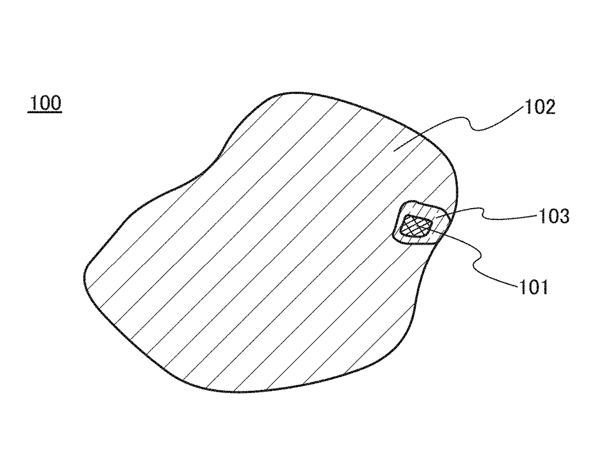
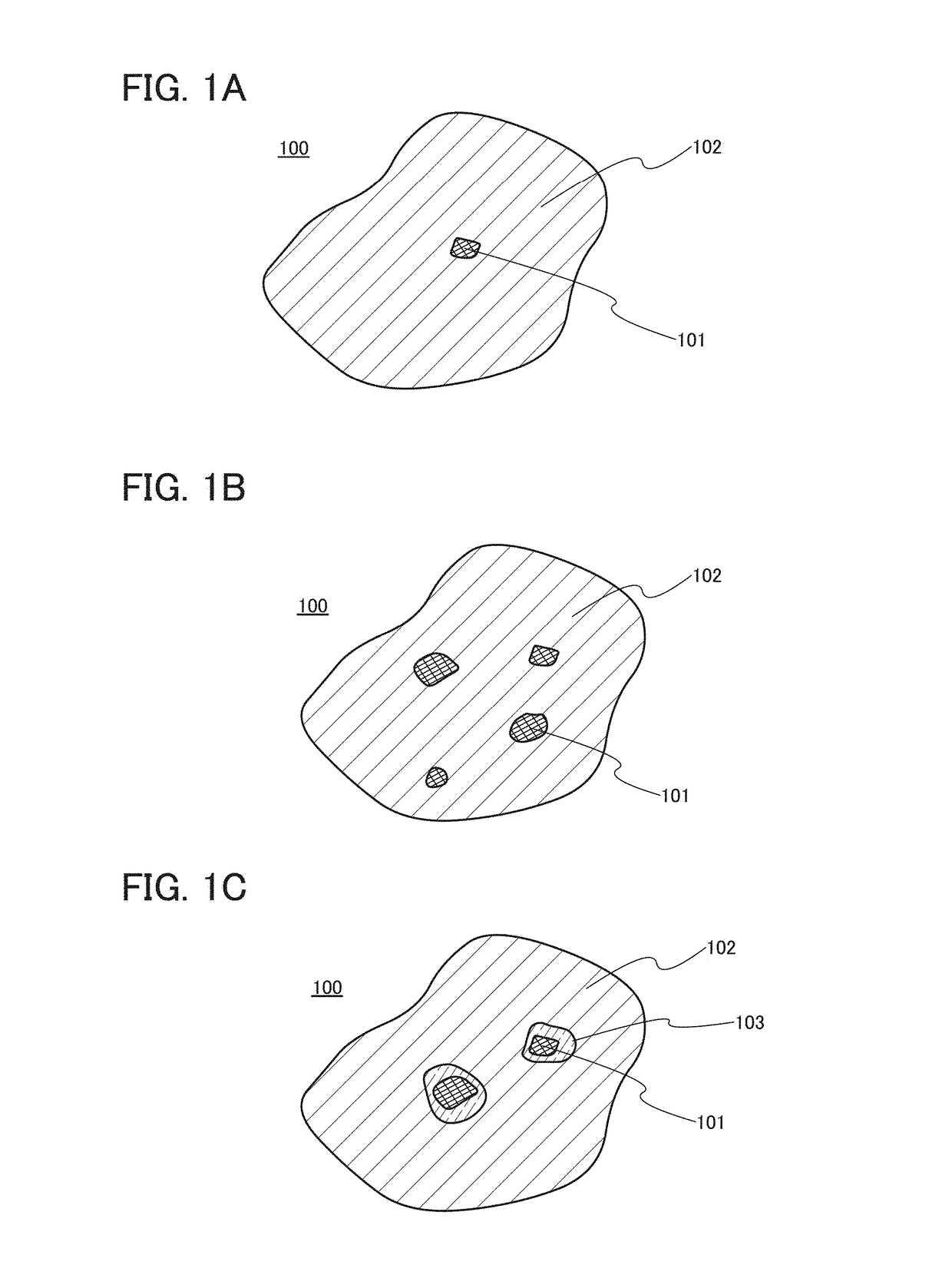
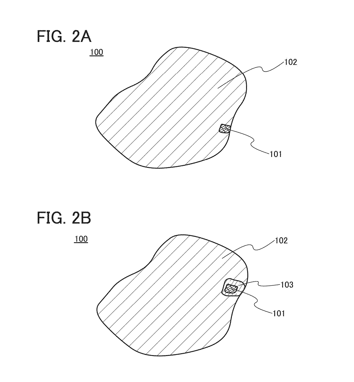
[0067]In this embodiment, a negative electrode active material of one embodiment of the present invention is described.

[0068]In the case where silicon, a material alloyed and dealloyed with lithium, is used as a negative electrode active material, a capacity can be increased compared with the case where graphite, a conventional negative electrode active material, is used. Graphite has a theoretical capacity of 372 mAh / g, whereas silicon has a theoretical capacity of 4200 mAh / g, that is over ten times as much as that of graphite.

[0069]However, a material that is alloyed and dealloyed with lithium (e.g., silicon) greatly expands and contracts with reception and release of carrier ions in charge and discharge cycles; therefore, when the amount of carrier ions received by the material increases, deformation or a crack would be generated. Then, the active material might be separated from a current collector or pulverized, which might lead to difficulty of maintaining a function for a lit...

embodiment 2

[0112]In this embodiment, an electrode including the negative electrode active material shown in Embodiment 1 is described.

[Structure of Negative Electrode]

[0113]FIG. 3A is an overhead view of a negative electrode 200, and FIG. 3B is a cross-sectional view of a portion surrounded by a dashed line in FIG. 3A. The negative electrode 200 has a structure in which a negative electrode active material layer 202 is provided over a negative electrode current collector 201. Although the negative electrode active material layers 202 are provided so that the negative electrode current collector 201 is sandwiched therebetween in FIGS. 3A and 3B, the negative electrode active material layer 202 may be formed over only one surface of the negative electrode current collector 201. The negative electrode active material layer 202 includes a negative electrode active material. For the negative electrode active material, the negative electrode active material shown in Embodiment 1 can be used.

[0114]Th...

embodiment 3

[0156]In this embodiment, an example of a power storage device using the electrode shown in Embodiment 2 is described.

[Thin Storage Battery]

[0157]FIG. 5 illustrates a thin storage battery as an example of a power storage device. When a flexible thin storage battery is used in an electronic device at least part of which is flexible, the storage battery can be bent as the electronic device is bent.

[0158]FIG. 5 illustrates the appearance of a thin storage battery 500. FIG. 6A is a cross-sectional view taken along dashed-dotted line A1-A2 in FIG. 5, and FIG. 6B is a cross-sectional view taken along dashed-dotted line B1-B2 in FIG. 5. The thin storage battery 500 includes a positive electrode 503 including a positive electrode current collector 501 and a positive electrode active material layer 502, a negative electrode 506 including a negative electrode current collector 504 and a negative electrode active material layer 505, a separator 507, an electrolytic solution 508, and an exterio...


PUM

PropertyMeasurementUnit
crystallite sizeaaaaaaaaaa
particle sizeaaaaaaaaaa
crystallite sizeaaaaaaaaaa

Abstract

A power storage device with high capacity is provided. Alternatively, a power storage device with excellent cycle characteristics is provided. Alternatively, a power storage device with high charge and discharge efficiency is provided. Alternatively, a power storage device with a long lifetime is provided. A negative electrode active material includes a first region and a second region. The first region includes at least one element selected from Si, Mg, Ca, Ga, Al, Ge, Sn, Pb, Sb, Bi, Ag, Zn, Cd, As, Hg, and In. The second region includes oxygen and the same element as the one included in the first region. The crystallite size of the element included in the first region is larger than or equal to 1 nm and smaller than or equal to 10 nm.

Description

TECHNICAL FIELD[0001]The present invention relates to an object, a method, or a manufacturing method. In addition, the present invention relates to a process, a machine, manufacture, or a composition of matter. In particular, one embodiment of the present invention relates to a semiconductor device, a display device, a light-emitting device, a power storage device, a storage device, a driving method thereof, or a manufacturing method thereof. In particular, one embodiment of the present invention relates to a power storage device and a manufacturing method thereof.BACKGROUND ART[0002]In recent years, secondary batteries such as lithium-ion secondary batteries, lithium-ion capacitors, and air cells have been actively developed. In particular, demand for lithium-ion secondary batteries with high output and high energy density has rapidly grown with the development of the semiconductor industry, for electronic devices, for example, portable information terminals such as cell phones, sm...

Claims


Application Information

Patent Timeline
Patent Type & Authority Patents(United States)
IPC IPC(8): H01M4/13H01M4/36H01M4/38H01M4/48H01M10/0525H01G11/50H01M4/134H01M10/052H01G11/06H01G11/24H01M4/02
CPCH01M4/386H01G11/06H01G11/24H01G11/50H01M4/13H01M4/134H01M4/38H01M4/48H01M10/052H01M10/0525H01M4/366Y02E60/13H01M2004/027Y02E60/10
Inventor INOUE, NOBUHIROOGINO, KIYOFUMI
Owner SEMICON ENERGY LAB CO LTD
Why Eureka
Try Eureka