
Power storage device and electronic device

a power storage device and electronic device technology, applied in the direction of non-aqueous electrolyte cells, sustainable manufacturing/processing, batteries, etc., can solve the problems of high temperature inside the power storage device, low flash point, volatile ethylene carbonate but also many organic solvents, etc., to achieve high capacity, high energy density, and high reliability. the effect of power storag

Active Publication Date: 2019-12-03
SEMICON ENERGY LAB CO LTD
View PDF38 Cites 1 Cited by
  • Summary
  • Abstract
  • Description
  • Claims
  • Application Information

AI Technical Summary

Benefits of technology

[0024]Furthermore, one embodiment of the present invention can provide a power storage device with high capacity. Furthermore, one embodiment of the present invention can provide a power storage device with high energy density. Furthermore, one embodiment of the present invention can provide a highly reliable power storage device. Furthermore, one embodiment of the present invention can provide a power storage device with a long lifetime.
[0025]Furthermore, one embodiment of the present invention can provide a power storage device with reduced irreversible capacity. Furthermore, one embodiment of the present invention can provide a power storage device in which a decomposition reaction of an electrolytic solution is inhibited and a decrease in capacity with charge and discharge cycles is prevented. Furthermore, one embodiment of the present invention makes it possible to reduce or inhibit the decomposition reaction of an electrolytic solution, which speeds up at high temperature, and to prevent a decrease in charge and discharge capacity in charge and discharge at high temperature, in order to extend the operating temperature range of a power storage device.
[0026]Furthermore, one embodiment of the present invention can increase a yield of a power storage device. Furthermore, one embodiment of the present invention can provide a novel power storage device, a novel electrode, or the like.
[0027]Note that the description of these effects does not disturb the existence of other effects. Note that one embodiment of the present invention does not necessarily have all the effects. Note that other effects will be apparent from and can be derived from the description of the specification, the drawings, the claims, and the like.

Problems solved by technology

However, not only ethylene carbonate but also many organic solvents have volatility and a low flash point.
For this reason, in the case of using an organic solvent for an electrolytic solution for a power storage device, the temperature inside the power storage device might rise due to a short circuit, overcharge, or the like and the power storage device might burst or catch fire.

Method used


Image

  • Power storage device and electronic device
  • Power storage device and electronic device
  • Power storage device and electronic device

Examples


embodiment 1

[0076]In this embodiment, an example of the structure of a power storage device of one embodiment of the present invention is described.

[Structure of Power Storage Device]

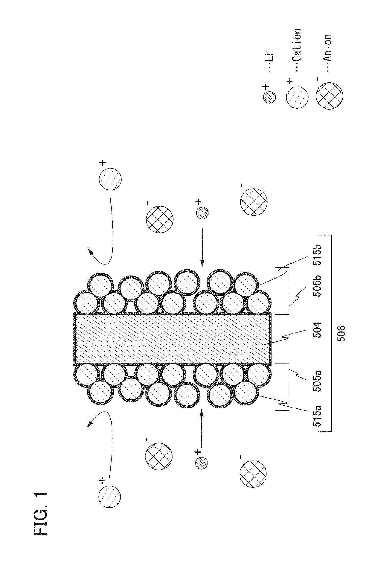
[0077]Here, an example of the power storage device of one embodiment of the present invention is described using a drawing. First, a reaction that occurs between a negative electrode and an electrolytic solution of the power storage device is described using FIG. 1. A negative electrode 506 illustrated in FIG. 1 includes a negative electrode current collector 504 and a negative electrode active material layer 505a and a negative electrode active material layer 505b that face each other with the negative electrode current collector 504 therebetween. Furthermore, a coating film 515a in contact with the negative electrode active material layer 505a and a coating film 515b in contact with the negative electrode active material layer 505b are included.

[0078]Note that “coating film” in one embodiment of the present inven...

embodiment 2

[0168]In this embodiment, a nonaqueous solvent used in a power storage device of one embodiment of the present invention is described.

[0169]A nonaqueous solvent used in a power storage device relating to one embodiment of the present invention preferably contains an ionic liquid. Either one kind of ionic liquid or a combination of some kinds of ionic liquids is used. The ionic liquid is composed of cations and anions. The ionic liquid contains organic cations and anions.

[0170]As the organic cation, an aromatic cation or an aliphatic onium cation such as a quaternary ammonium cation, a tertiary sulfonium cation, or a quaternary phosphonium cation is preferably used.

[0171]An aromatic cation is preferably a cation containing a five-membered heteroaromatic ring. Examples of the cation containing a five-membered heteroaromatic ring are a benzimidazolium cation, a benzoxazolium cation, and a benzothiazolium cation. Examples of the cation containing a five-membered heteroaromatic ring, whi...

embodiment 3

[0195]In this embodiment, specific structures and fabricating methods of a positive electrode and a negative electrode that can be used for one embodiment of the present invention are described.

[0196]For the negative electrode current collector 504 and the positive electrode current collector 501, the materials for the negative electrode current collector 504 and the positive electrode current collector 501 that are described in Embodiment 1 can be used.

[0197]As a negative electrode active material, for example, a carbon-based material, an alloy-based material, or the like can be used. As the carbon-based material, graphite, graphitizing carbon (soft carbon), non-graphitizing carbon (hard carbon), a carbon nanotube, graphene, carbon black, and the like are given. As graphite, artificial graphite such as meso-carbon microbeads (MCMB), coke-based artificial graphite, and pitch-based artificial graphite and natural graphite such as spherical natural graphite are given.

[0198]Graphite ha...


PUM

PropertyMeasurementUnit
temperatureaaaaaaaaaa
operating temperatureaaaaaaaaaa

Abstract

A power storage device with high capacity is provided. Alternatively, a power storage device with high energy density is provided. Alternatively, a highly reliable power storage device is provided. Alternatively, a long-life power storage device is provided.A power storage device is characterized by comprising a separator, a first electrode, a second electrode, an electrolytic solution, in which the separator is provided between the first electrode and the second electrode, the first electrode includes an active material layer and a current collector, the first electrode includes a pair of coating films between which the current collector is sandwiched, the active material layer includes a region in contact with the current collector, the active material layer includes a region in contact with at least one of the pair of coating films, and the electrolytic solution includes an alkali metal salt and an ionic liquid.

Description

TECHNICAL FIELD[0001]One embodiment of the present invention relates to, for example, an object, a method, or a manufacturing method. Alternatively, one embodiment of the present invention relates to a process, a machine, manufacture, or a composition of matter (composition of matter). In particular, one embodiment of the present invention relates to a semiconductor device, a display device, a light-emitting device, a power storage device, a storage device, a driving method thereof, or a manufacturing method thereof. In particular, one embodiment of the present invention relates to a power storage device and a manufacturing method thereof.[0002]Note that a power storage device in this specification refers to every element and / or device having a function of storing electric power. For example, a storage battery such as a lithium-ion secondary battery, a lithium-ion capacitor, an electric double layer capacitor, and the like are included.BACKGROUND ART[0003]In recent years, a variety ...

Claims


Application Information

Patent Timeline
Patent Type & Authority Patents(United States)
IPC IPC(8): H01G11/06H01M10/05H01M10/0569H01G11/26H01G11/62H01M10/058H01G11/60H01G11/64H01M2/14H01M4/134H01M4/66H01M10/0525H01M10/0567H01M4/36H01M6/16H01M4/133H01M4/02H01M4/136H01M4/58
CPCH01M2/14H01M4/134H01M10/0567H01M10/0525H01G11/62H01M4/662H01M4/366H01G11/64H01G11/06H01G11/26H01M10/058H01G11/60H01M4/663H01M10/0569H01M4/5825H01M4/136H01M6/16H01M4/133H01M2004/028H01M2004/027Y02E60/13H01M2300/0045Y02T10/7011Y02T10/70Y02E60/10Y02P70/50H01M4/13H01M2220/30
Inventor ISHIKAWA, JUNNARITA, KAZUHEIOGUNI, TEPPEIUCHIDA, AYA
Owner SEMICON ENERGY LAB CO LTD
Learn More