Power storage device electrode, method for manufacturing the same, power storage device, and electronic device

a technology of power storage device and electrode, which is applied in the direction of secondary battery servicing/maintenance, cell components, sustainable manufacturing/processing, etc., can solve the problems of deterioration gradually, the reaction potential of the negative electrode of a lithium-ion secondary battery and a lithium-ion capacitor is out of the potential windows of almost all electrolytic solutions, and cannot be said that such a surface film is sufficiently stable, etc., to achieve high adhesion, reduce irreversible capacity capacity capacity capacity capacity capacity capacity capacity capacity capacity capacity capacity capacity capacity capacity capacity capacity capacity capacity capacity capacity

Pending Publication Date: 2021-10-07
SEMICON ENERGY LAB CO LTD
View PDF5 Cites 0 Cited by
  • Summary
  • Abstract
  • Description
  • Claims
  • Application Information

AI Technical Summary

Benefits of technology

[0011]An object of one embodiment of the present invention is to provide a highly reliable power storage device. An object of one embodiment of the present invention is to provide a long-life power storage device.
[0013]An object of one embodiment of the present invention is to reduce irreversible capacity which causes a decrease in the charge and discharge capacity and to reduce or inhibit the electrochemical decomposition of an electrolytic solution and the like on a surface of an electrode. An object of one embodiment of the present invention is to reduce or inhibit the decomposition reaction of an electrolytic solution and the like occurring as a side reaction in repeated charging and discharging of a power storage device in order to improve the cycle characteristics of the power storage device. An object of one embodiment of the present invention is to reduce or inhibit the decomposition reaction of an electrolytic solution, which speeds up at high temperature, and to prevent a decrease in charge and discharge capacity in charging and discharging at high temperature, in order to extend the operating temperature range of a power storage device.
[0025]One embodiment of the present invention makes it possible to provide a power storage device with high reliability. One embodiment of the present invention makes it possible to provide a power storage device with a long lifetime.
[0026]One embodiment of the present invention makes it possible to provide a power storage device electrode having high adhesion between a current collector and an electrode layer. One embodiment of the present invention makes it possible to provide a power storage device electrode in which deterioration due to deformation is inhibited. One embodiment of the present invention makes it possible to provide a power storage device electrode in which deterioration due to repeated charging and discharging of a power storage device is inhibited.
[0027]One embodiment of the present invention makes it possible to reduce irreversible capacity which causes a decrease in the charge and discharge capacity and to reduce or inhibit the electrochemical decomposition of an electrolytic solution and the like on a surface of an electrode. One embodiment of the present invention makes it possible to reduce or inhibit the decomposition reaction of an electrolytic solution and the like occurring as a side reaction in repeated charging and discharging of a power storage device in order to improve the cycle characteristics of the power storage device. One embodiment of the present invention makes it possible to reduce or inhibit the decomposition reaction of an electrolytic solution, which speeds up at high temperature, and to prevent a decrease in charge and discharge capacity in charging and discharging at high temperature, in order to extend the operating temperature range of a power storage device. One embodiment of the present invention makes it possible to provide a novel electrode. One embodiment of the present invention makes it possible to provide a novel power storage device. Note that the description of these effects does not disturb the existence of other effects. One embodiment of the present invention does not necessarily achieve all the above effects. Other effects will be apparent from and can be derived from the description of the specification, the drawings, the claims, and the like.

Problems solved by technology

However, reaction potentials of the negative electrodes of a lithium-ion secondary battery and a lithium-ion capacitor are out of the potential windows of almost all electrolytic solutions.
However, at the same time as battery reaction, the electrolytic solution is gradually decomposed and a surface film is formed due to the decomposition product, and thus, deterioration gradually proceeds.
Therefore, it cannot be said that such a surface film is sufficiently stable.
In addition, the formation of the surface film causes irreversible capacity, resulting in a partial loss of charge and discharge capacity.
Further, the surface film has extremely small electric conductivity, which lowers the electric conductivity of an electrode while a battery is charged and discharged.
Consequently, the charge and discharge capacity of the battery is low, and the cycle life of the battery is short due to local charge and discharge.
Therefore, as in the negative electrode, irreversible capacity is caused in the positive electrode, resulting in a decrease in charge and discharge capacity.

Method used


Image

  • Power storage device electrode, method for manufacturing the same, power storage device, and electronic device
  • Power storage device electrode, method for manufacturing the same, power storage device, and electronic device
  • Power storage device electrode, method for manufacturing the same, power storage device, and electronic device

Examples


embodiment 1

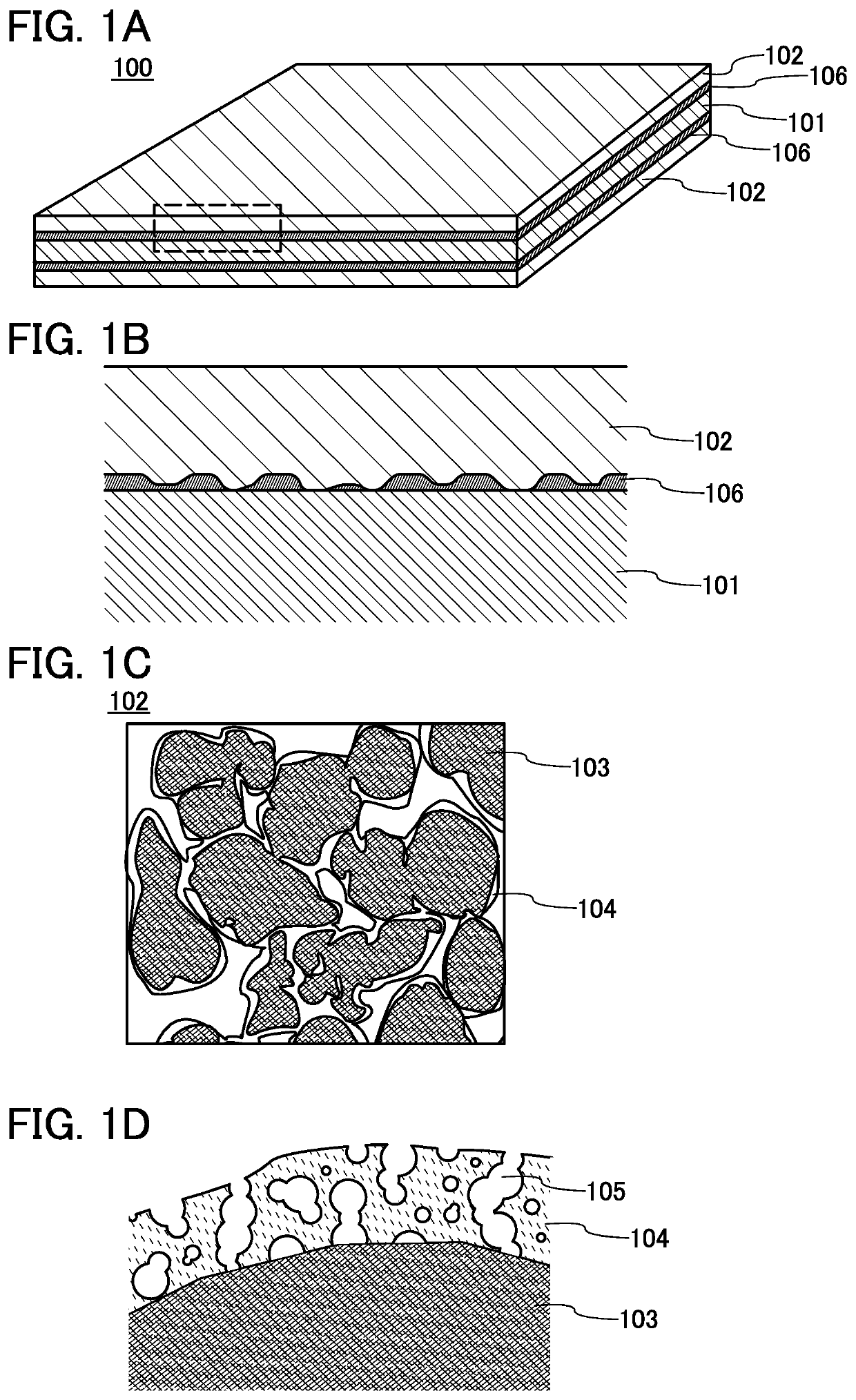
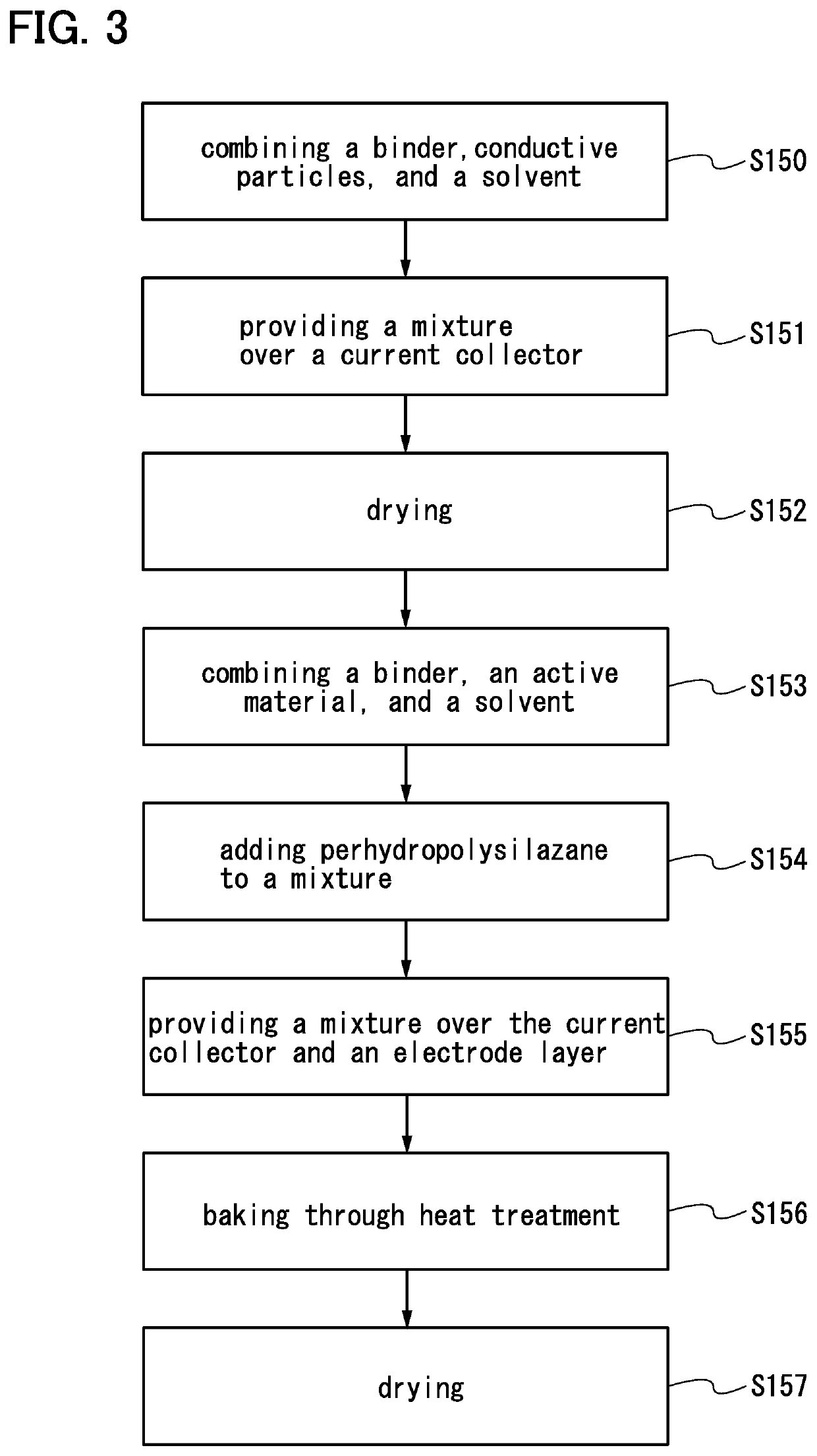
[0056]In this embodiment, a layer for increasing adhesion is provided between a current collector and an active material layer. In addition, a coating film is formed on an active material with the use of perhydropolysilazane.

[0057]With the use of perhydropolysilazane, a coating film can be formed on a surface of an active material in a power storage device electrode. Such a coating film can inhibit reaction between the active material and an electrolytic solution and reduce irreversible capacity.

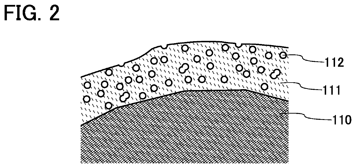
[0058]When a coating film is formed on a surface of an active material of a power storage device electrode with the use of perhydropolysilazane and a binder having a carboxyl group (—COOH) is used, a porous coating film can be formed as a result of interaction between the carboxyl group and perhydropolysilazane. An electrode including this porous coating film has better cycle characteristics.

[0059]“The coating film is porous” means that the coating film has a number of pores on its surface o...

embodiment 2

[0142]In this embodiment, the structures of power storage devices including the electrode described in Embodiment 1 will be described with reference to FIGS. 11A to 11C, FIGS. 12A and 12B, FIGS. 13A and 13B, and FIGS. 14A to 14E. Structural examples of power storage devices (storage batteries) will be described with reference to FIGS. 15A and 15B, FIGS. 16A1, 16A2, 16B1, and 16B2, FIGS. 17A and 17B, FIGS. 18A and 18B, and FIG. 19. Examples of electronic devices will be described with reference to FIGS. 20A and 20B.

(Coin-Type Storage Battery)

[0143]FIG. 11A is an external view of a coin-type (single-layer flat type) storage battery, and FIG. 11B is a cross-sectional view thereof.

[0144]In a coin-type storage battery 300, a positive electrode can 301 doubling as a positive electrode terminal and a negative electrode can 302 doubling as a negative electrode terminal are insulated from each other and sealed by a gasket 303 made of polypropylene or the like. Here, as at least one of a posi...

example 1

[0202]In this example, the electrode described in Embodiment 1 was manufactured and the electrode strength was evaluated. A half cell and a full cell were manufactured using the electrode and their characteristics were evaluated.

(Formation of Electrode)

[0203]As described in Embodiment 1, slurry was prepared to form an electrode.

[0204]Slurry A was prepared in the following manner: acetylene black (the surface area was 63 m2 / g, and the grain diameter was approximately 30 nm) was added to N-methyl-2-pyrrolidone (NMP) including 12 wt % polyvinylidene fluoride (PVdF), and the mixture was stirred and mixed in a mixer at 2000 rpm for 25 minutes. The PVdF was one to which a carboxyl group was added.

[0205]Slurry B was prepared by mixing an aqueous solution of polyarylamine (product name: PAA-15C) and an anchor coat agent (product name: Super Collophite). Polyarylamine is a compound having an amino group. The anchor coat agent contains graphite and water in a weight ratio of 89.5:10.5 (wt %)....


PUM

PropertyMeasurementUnit
temperatureaaaaaaaaaa
wavenumberaaaaaaaaaa
thicknessaaaaaaaaaa

Abstract

To provide a highly reliable power storage device. To provide a long-life power storage device. To provide a power storage device electrode having high adhesion with a current collector. To reduce or inhibit electrochemical decomposition of an electrolytic solution or the like on a surface of an electrode. The power storage device electrode includes a current collector and a second electrode layer provided over the current collector and including a second binder and an active material. A first electrode layer including a first binder and conductive particles is provided between the current collector and the second electrode layer. At least part of a surface of the active material is provided with a coating film, and the coating film is porous.

Description

BACKGROUND OF THE INVENTION1. Field of the Invention[0001]The present invention relates to an object, a method, or a manufacturing method. In addition, the present invention relates to a process, a machine, manufacture, or a composition of matter. One embodiment of the present invention relates to a semiconductor device, a display device, a light-emitting device, a power storage device, a driving method thereof, and a manufacturing method thereof. In particular, one embodiment of the present invention relates to a power storage device electrode and a method for manufacturing the power storage device electrode.2. Description of the Related Art[0002]In recent years, various power storage devices such as secondary batteries including lithium-ion secondary batteries and the like, lithium ion capacitors, and air cells have been actively developed. In particular, demand for lithium-ion secondary batteries with high output and high energy density has rapidly grown with the development of t...

Claims


Application Information

Patent Timeline
Patent Type & Authority Applications(United States)
IPC IPC(8): H01M4/13H01M4/04H01M4/139H01M4/62H01M10/42H01M4/36H01M4/02
CPCH01M4/13H01M4/0404H01M4/139H01M10/052H01M10/4235H01M4/366H01M4/622H01M4/625Y02E60/10Y02P70/50
Inventor IKENUMA, TATSUYAKURIKI, KAZUTAKA
Owner SEMICON ENERGY LAB CO LTD
Why Eureka
Try Eureka