Lithium secondary battery manufacturing method comprising forming lithium metal layer and lithium secondary battery

a secondary battery and manufacturing method technology, applied in the direction of cell components, final product manufacturing, sustainable manufacturing/processing, etc., can solve the problems of reducing the capacity of the battery, not always reducing the deformation of the negative electrode to a satisfying level, and the active material of the negative electrode fails to contribute to the charge and discharge, etc., to achieve the effect of reducing the deformation of the negative electrode, avoiding a decrease in the charge and discharge capacity, and reducing the deformation

Inactive Publication Date: 2013-12-10
PANASONIC CORP
View PDF31 Cites 1 Cited by
  • Summary
  • Abstract
  • Description
  • Claims
  • Application Information

AI Technical Summary

Benefits of technology

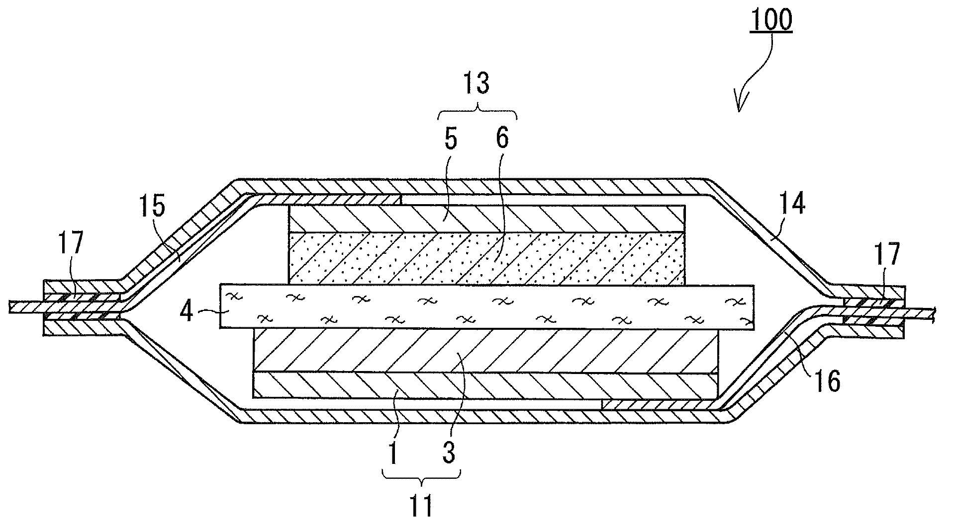
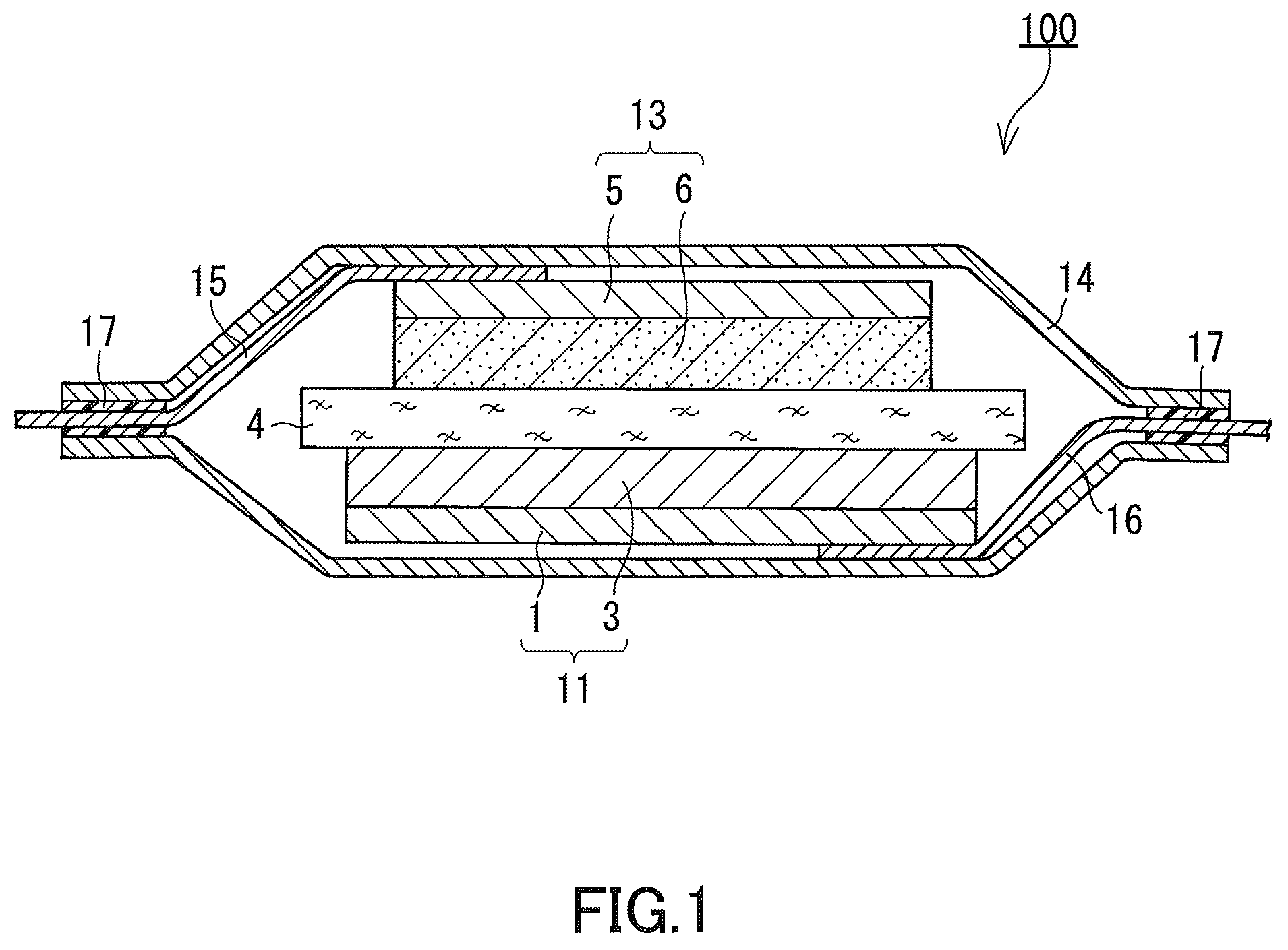
[0025]In the present invention, the lithium metal layer is formed on the negative electrode active material layer before the battery is assembled. Thereby, lithium is occluded in the negative electrode active material layer, making it possible to elongate the negative electrode current collector in advance. Therefore, it is possible to alleviate or suppress the deformation of the negative electrode during charge and discharge. Furthermore, a lithium-deficient lithium composite oxide is used as the positive electrode active material. That is, a space to occlude lithium is ensured in advance in the positive electrode. This makes it possible to avoid a decrease in the charge and discharge capacity due to the formation of the lithium metal layer on the negative electrode active material layer. In addition, it is possible to prevent an excess amount of lithium metal from being precipitated on the surface of the positive electrode or the negative electrode during charge and discharge. Therefore, the present invention can provide a high capacity lithium secondary battery in which the deformation of the negative electrode is reduced.

Problems solved by technology

Thus, repeated charges and discharges separate the negative electrode active material from the charge collector, and the negative electrode active material fails to contribute to the charge and discharge.
The deformation of the negative electrode is not preferable, either, because it leads directly to a decreased capacity of the battery.
However, the oblique deposition does not always reduce the deformation of the negative electrode to a satisfying level.
That is, it is difficult to control the amount of elongation, and it is difficult to apply the technique to mass production.
However, allowing the negative electrode active material layer to occlude lithium in advance results in that lithium is present in both of the positive electrode and the negative electrode when assembling the battery.
Moreover, an excess amount of lithium may possibly be precipitated on a surface of the positive electrode or the negative electrode during charge and discharge.

Method used


Image

  • Lithium secondary battery manufacturing method comprising forming lithium metal layer and lithium secondary battery
  • Lithium secondary battery manufacturing method comprising forming lithium metal layer and lithium secondary battery
  • Lithium secondary battery manufacturing method comprising forming lithium metal layer and lithium secondary battery

Examples


examples

[0082]

[0083](a) Fabrication of Negative Electrode Current Collector

[0084]As the material for the negative electrode current collector, a copper alloy foil with a thickness of 26 μm was prepared. The copper alloy foil was subject to press processing on its front and back surfaces so that projections, each having a rhomboidal shape in plane view and diagonal lines of 10×20 μm, are formed thereon at an interval of 30 μm. The height of the projections was set to 6 μm. Subsequently, a copper roughening plating layer with a thickness of 2 μm was formed on each of the surfaces of the copper alloy foil by an electrolytic copper plating method. Thus, a negative electrode current collector was obtained. The copper roughening plating layer had Ra, an arithmetic mean roughness according to JIS B 0601 (1994), of about 0.5 μm.

[0085](b) Formation of the Negative Electrode Active Material Layer

[0086]Next, a negative electrode active material layer containing silicon and a silicon oxide was formed o...


PUM

PropertyMeasurementUnit
temperatureaaaaaaaaaa
elongation percentageaaaaaaaaaa

Abstract

A negative electrode active material layer 3 containing at least one element selected from the group consisting of silicon, germanium, and tin is formed on a negative electrode collector 1. A negative electrode 11 is prepared by forming a lithium metal layer on the negative electrode active material layer 3. Also prepared is a positive electrode 11 having a configuration in which a positive electrode active material layer 6 containing a composite oxide represented by a general formula Li1-xMO2, where 0.2≦x≦0.6, and M includes at least one transition metal selected from the group consisting of cobalt, nickel, and manganese, is formed on a positive electrode current collector 5. A lithium secondary battery 100 is assembled from the negative electrode 13, the positive electrode 11, and a separator 4.

Description

RELATED APPLICATIONS[0001]This application is the U.S. National Phase under 35 U.S.C. §371 of International Application No. PCT / JP2009 / 003662, filed on Jul. 31, 2009, which in turn claims the benefit of Japanese Application No. 2008-200765, filed on Aug. 4, 2008, the disclosures of which Applications are incorporated by reference herein.TECHNICAL FIELD[0002]The present invention relates to a lithium secondary battery manufacturing method and a lithium secondary battery.BACKGROUND ART[0003]In recent years, as portable apparatuses have been downsized and multifunctionalized, there is a strong demand for increasing the capacities of the batteries as power supplies for the portable apparatuses. Carbon, which is a negative electrode active material, mainly used in lithium secondary batteries today, has a theoretical capacity of 372 mAh / g. As an active material capable of increasing the battery capacity more than carbon, there has been developed a negative electrode using an element, such...

Claims


Application Information

Patent Timeline
Patent Type & Authority Patents(United States)
IPC IPC(8): H01M4/04H01M4/52H01M4/58H01M4/64H01M4/485H01M4/50H01M4/134H01M10/36
CPCH01M4/0423H01M4/134H01M4/1395H01M4/366H01M4/382H01M10/052H01M4/131H01M4/1391H01M4/505H01M4/525H01M2004/027Y02E60/122H01M4/38Y10T29/49115Y10T29/49108Y02E60/10Y02P70/50
Inventor YAGI, HIROMASAHONDA, KAZUYOSHI
Owner PANASONIC CORP
Why Eureka
Try Eureka