
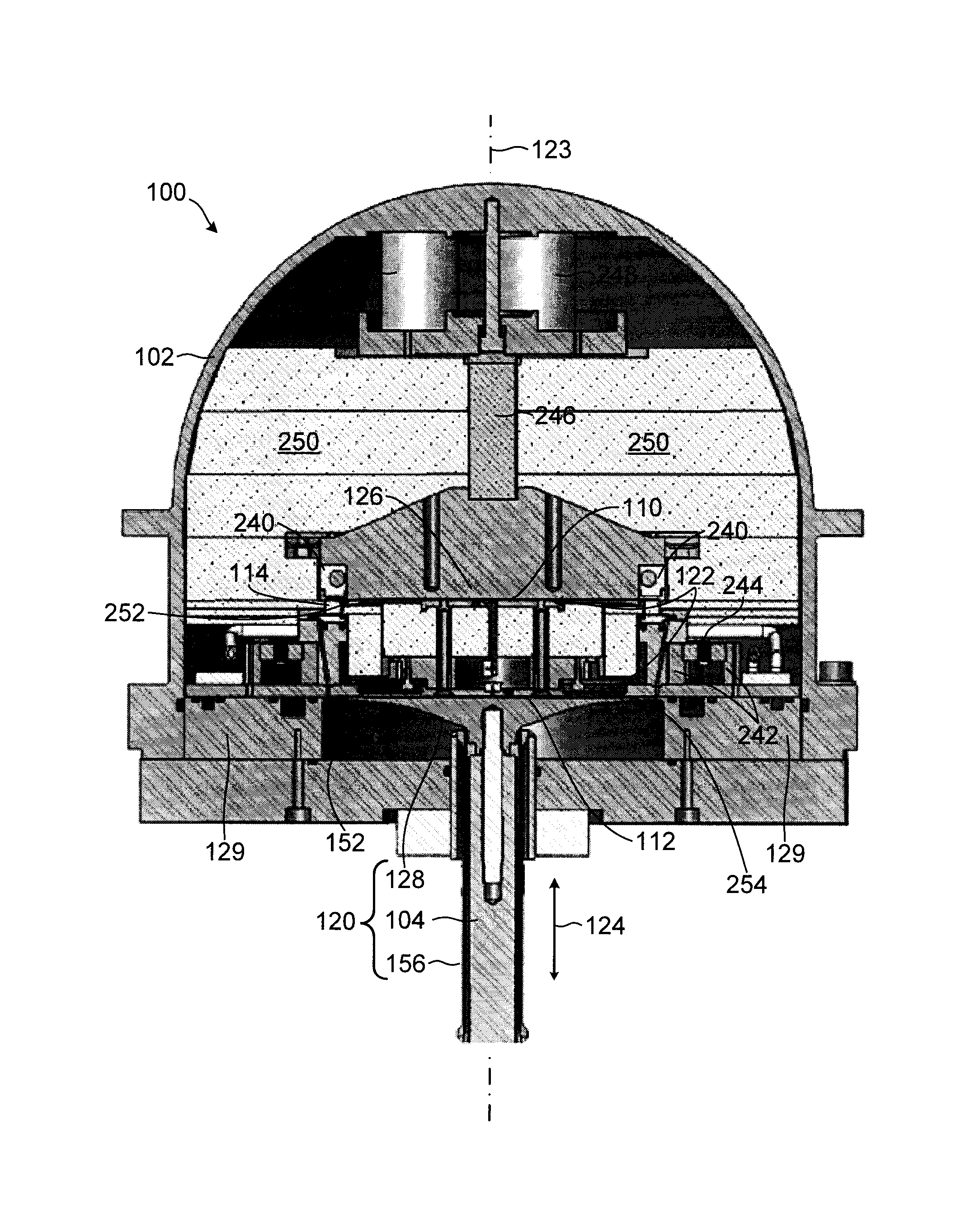
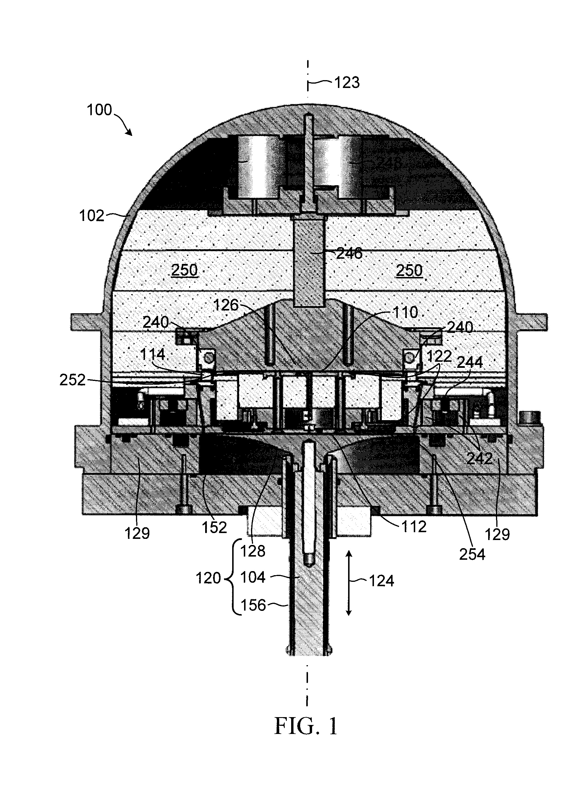
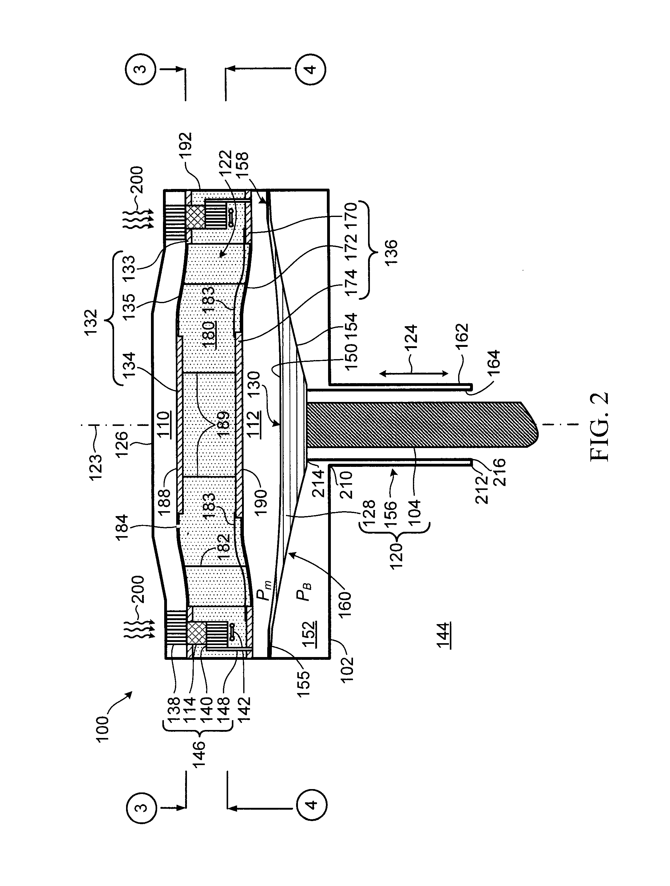
Stirling cycle transducer for converting between thermal energy and mechanical energy

a transducer and thermal energy technology, applied in the direction of stirling type engines, machines/engines, hot gas positive displacement engine plants, etc., can solve the problems of difficulty in making high pressure and high temperature reciprocating or rotating gas seals, and affecting the operation of stirling engines. , to achieve the effect of preventing significant gaseous communication, reducing the temperature of the working gas flowing, and reducing hysteresis losses

Active Publication Date: 2016-07-19
ETALIM
View PDF99 Cites 0 Cited by
  • Summary
  • Abstract
  • Description
  • Claims
  • Application Information

AI Technical Summary

Benefits of technology

[0019]The thickness profile of the flexure may be selected to cause the flexure to have an effective area to impart reciprocating motion to the displacer at the desired phase angle in absence of reciprocating complementary vibration of the apparatus.
[0056]The high thermal conductivity wall may include a material having a first thermal expansion rate and the insulating spacer may include a material having a second thermal expansion rate, and the materials may be selected to provide a sufficiently close match between thermal expansion rates to reduce mechanical stresses at an interface between the wall and the spacer when operating at high temperature.

Problems solved by technology

The adoption of Stirling engines has been hampered in part by the cost of high temperature materials, and the difficulty of making high pressure and high temperature reciprocating or rotating gas seals.
Furthermore the need for relatively large heat exchangers and low specific power in comparison to internal combustion engines has also hampered widespread adoption of Stirling engines.
Specific power refers to output power per unit of mass, volume or area and low specific power results in higher material costs for the engine for a given output power.
Unfortunately at reasonable operating frequencies the wavelength of sound waves is however too long to allow for compact engines and consequently results in relatively low specific power.
Several diaphragm engines have been proposed and built, but generally have low specific power (i.e. the power produced per unit volume is low).

Method used


Image

  • Stirling cycle transducer for converting between thermal energy and mechanical energy
  • Stirling cycle transducer for converting between thermal energy and mechanical energy
  • Stirling cycle transducer for converting between thermal energy and mechanical energy

Examples


Embodiment Construction

Introduction

[0076]The output power of a Stirling engine Wout empirically follows the formula:

[0077]Wout=NW·Pm·f·Vs⁢Th-TcTh+Tc,Eqn⁢⁢1

where[0078]NW is the “West” number (“Principles and Applications of Stirling Engines”, Colin D. West, Van Nostrand Reinhold, 1986);[0079]Pm, is the mean working-gas pressure;[0080]f is the operating frequency;[0081]Th, Tc, are the respective hot and cold side temperatures; and[0082]Vs is the volume swept by the power piston.

[0083]In a diaphragm engine, the diaphragm is usually fabricated from a metal such as steel, which restricts a maximum operating deflection of the diaphragm thus placing a constraint on the swept volume VS in Eqn 1. The swept volume constraint may be compensated for by operating at increased frequency, increased temperature differential, and / or increased pressure in order to provide a greater power output for a particular engine. The West number NW accounts for losses and an engine design that minimizes losses will have a greater Wes...


PUM


Abstract

The apparatus includes a housing, a compression chamber disposed in the housing and having at least a first interface operable to vary a volume of the compression chamber, an expansion chamber disposed in the housing and having a second interface operable to vary a volume of at least the expansion chamber, and a thermal regenerator in fluid communication with each of the compression chamber and the expansion chamber. The thermal regenerator is operable to alternatively receive thermal energy from gas flowing in a first direction through the regenerator and to deliver the thermal energy to gas flowing in a direction opposite to the first direction through the regenerator. The compression chamber, the expansion chamber, and the regenerator together define a working volume for containing a pressurized working gas. Each of the first and second interfaces are configured for reciprocating motion in a direction aligned with a transducer axis, the reciprocating motion being operable to cause a periodic exchange of working gas between the expansion and the compression chambers. In one aspect, at least one of the first and second interfaces includes a resilient diaphragm, and a cylindrical tube spring coupled between the diaphragm and the housing, the tube spring being configured to elastically deform in a direction generally aligned with the transducer axis in response to forces imparted on the tube spring by the diaphragm to cause the at least one of the first and second interfaces to have a desired natural frequency. In another aspect the apparatus includes a first heat exchanger in communication with the expansion chamber, a second heat exchanger in communication with the compression chamber, the thermal regenerator is disposed between the first and second heat exchangers, and each of the first and second heat exchangers are peripherally disposed within the housing with respect to the transducer axis and configured to receive working gas flowing to or from the respective chambers and to redirect the working gas flow through the regenerator.

Description

RELATED APPLICATIONS[0001]This application is a 371 US National Phase of International Application No. PCT / CA2010 / 001092, filed Jul. 12, 2010 and claims the benefit of U.S. Application No. 61 / 213,760, filed Jul. 10, 2009. The entire teachings of the above applications are incorporated herein by reference.BACKGROUND OF THE INVENTION[0002]1. Field of Invention[0003]This invention relates generally to transducers and more particularly to a Stirling cycle transducer for converting thermal energy into mechanical energy or for converting mechanical energy into thermal energy.[0004]2. Description of Related Art[0005]Stirling cycle heat engines and heat pumps date back to 1816 and have been produced in many different configurations. Potential advantages of such Stirling cycle devices include high efficiency and high reliability. The adoption of Stirling engines has been hampered in part by the cost of high temperature materials, and the difficulty of making high pressure and high temperatur...

Claims


Application Information

Patent Timeline
Patent Type & Authority Patents(United States)
IPC IPC(8): F02G1/04F02G1/043F02G1/053
CPCF02G1/043F02G1/053F02G2243/52
Inventor STEINER, THOMAS WALTERMEDARD DE CHARDON, BRIACKANEMARU, TAKAO
Owner ETALIM
Learn More