
Crimp-on pipe connection accessory

a technology for connecting pipes and accessories, which is applied in the direction of non-disconnectible pipe joints, flanged joints, pipes/joints/fittings, etc., can solve the problems of degrading the fatigue resistance of the connector, degrading the quality of the crimp, and affecting the performance of the connector, so as to improve the resistance to rotational separation

Active Publication Date: 2016-07-26
PERMASWAGE
View PDF26 Cites 2 Cited by
  • Summary
  • Abstract
  • Description
  • Claims
  • Application Information

AI Technical Summary

Benefits of technology

The invention proposes a connection accessory for pipes that resists rotational separation after crimping without affecting other aspects of the assembly's mechanical performance. The accessory has an adhesive coated surface that prevents the adhesive from spreading during crimping and allows for a better seal at the fitting. The other surface of the accessory has a corrugated profile that encourages good axial retention between the accessory and the pipe. The adhesive is advantageously set back relative to the accessory surface to improve its compression during crimping. The adhesive coated collars on the accessory engage with the adhesive to establish a strong bond, even at the sacrifice of weaker areas between the collars.

Problems solved by technology

It should be noted here that, if the accessory is used for a screwed connection, there is a risk of any rotation of one of the fittings relative to the other fitting degrading the quality of the crimp.
Increasing the amplitude of the corrugations between the concave and convex portions is not very effective either, given that the material constituting the connector is often subject to only a small amount of work hardening, especially if that material is aluminum for reasons of lightness, with the result that increasing the crimping force does not greatly increase the radial pressure between the pipe and the connector; to the contrary, such corrugations can degrade the fatigue resistance of the connector.
However, if such particles are sufficiently hard not to be crushed during crimping, their hardness has the drawback that there is a risk of them causing cracks in the sleeve or in the end of the pipe, which seriously degrades fatigue performance.
In fact, the variety of options for adapting the connectors to improve resistance to rotation after crimping is restricted by the fact that in practice there is a requirement not to modify the conditions for fitting such connectors (or at least not to modify them significantly); these conditions are already sometimes very constraining, notably from the point of view of the accessibility of the pipes, which would appear to rule out further complicating the connector crimping conditions.

Method used


Image

  • Crimp-on pipe connection accessory
  • Crimp-on pipe connection accessory
  • Crimp-on pipe connection accessory

Examples


third embodiment

[0079]FIGS. 10 to 12 show the invention.

[0080]These figures show a connection accessory 50 formed primarily of a sleeve, which has externally a projecting convex portion 52 and a portion 53 coated with adhesive (see FIG. 10). The latter is crimped to the end of a pipe tube 54 (see FIG. 11) and then assembled by screwing of a nut-forming part 55 to a connecting fitting 56′ for example one adapted to be fitted to an inlet / outlet fitting of a fluid device or a fitting mounted at the end of another pipe tube.

[0081]The components of the accessory of the invention are in practice made of metal (e.g. stainless steel, aluminum alloy, titanium or titanium alloy, copper or copper alloy). The sleeve and the fitting can be in metals of identical or different compositions, as required.


PUM


Abstract

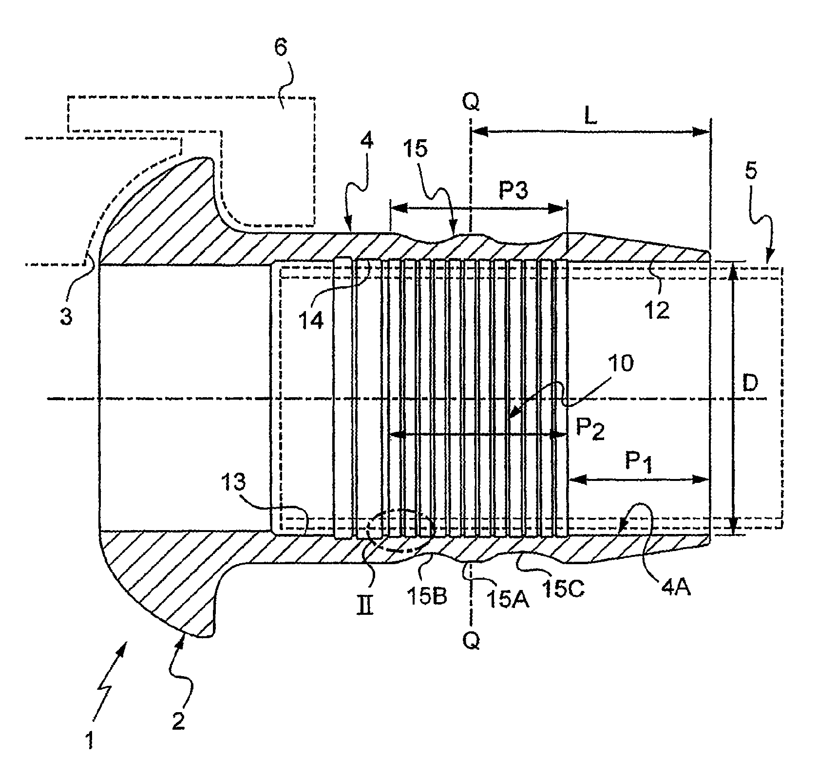
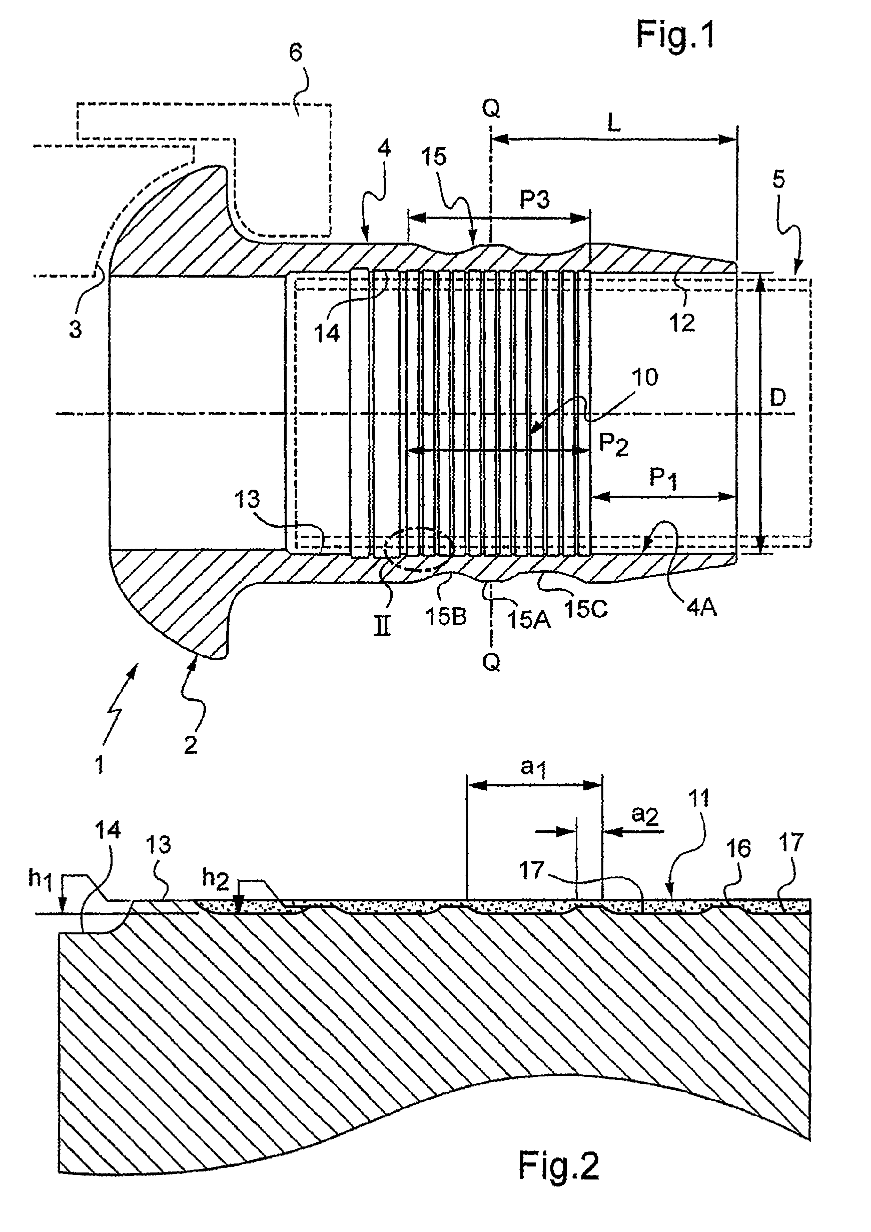
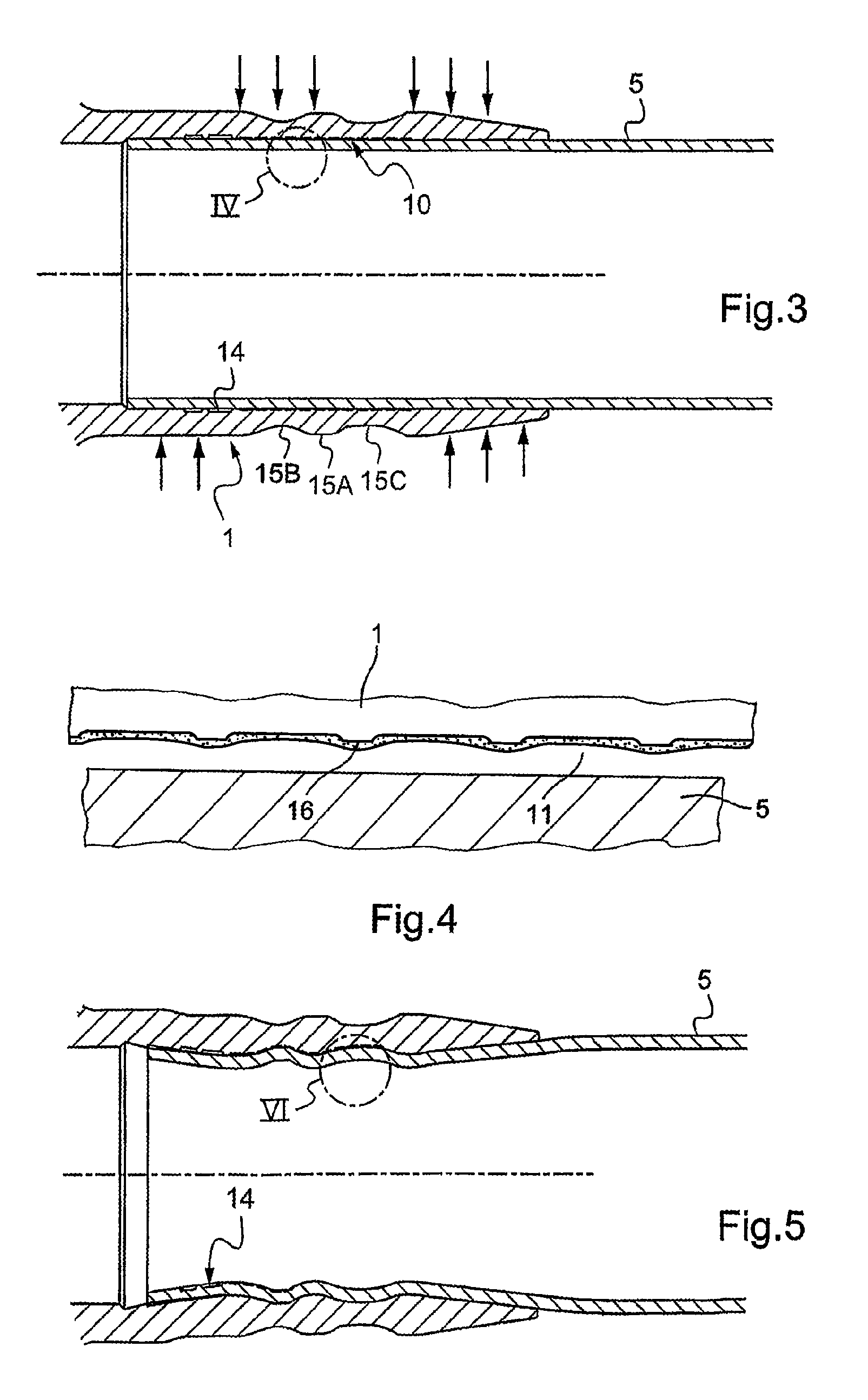
A pipe connection accessory 1 comprising a sleeve 4 designed to be crimped onto one end of a pipe tube and designed to engage at least indirectly with another pipe element, is characterized in that that surface 4A of the sleeve which is intended to come into crimped contact with the end of the tube comprises an adhesive-coated portion 10 comprising an adhesive made up of at least two components, one of which is encapsulated. This adhesive-coated portion is advantageously set back, preferably with projecting collars.

Description

FIELD[0001]The invention concerns an accessory for connecting pipes, the connection preferably, although not necessarily, being demountable.BACKGROUND[0002]A connection of this type is known in particular from the document U.S. Pat. No. 3,572,779, which describes a connection accessory formed of two parts crimped to the respective ends of two pipes; these two parts can be fastened to each other or screwed to each other.[0003]Also known is the document WO-82 / 02755, which discloses an accessory including a sleeve intended to be crimped to the end of a first pipe and a fitting adapted to establish a connection with a complementary fitting mounted at the end of another pipe; in the above document this sleeve and this fitting have different hardness (or ductility) properties, i.e. the sleeve is sufficiently ductile to enable fixing by crimping whereas the fitting is sufficiently hard to locate effectively against the complementary fitting to obtain a good seal. The above document propose...

Claims


Application Information

Patent Timeline
IPC IPC(8): F16L13/14F16L13/10F16L23/024
CPCF16L13/103F16L13/14F16L23/024
Inventor HERAUD, STEPHANEBERNARDOT, CHRISTIANLECROC, DANIEL
Owner PERMASWAGE
Learn More