Supercharge Your Innovation With Domain-Expert AI Agents!

Method for the non-destructive inspection of a test object of great material thickness by means of ultrasound, the use of a test probe for carrying out the method, an ultrasonic test probe, a control unit for an ultrasonic test probe and a device for the non-destructive inspection of a test object of great material thickness by means of ultrasound

a test object and non-destructive inspection technology, applied in the direction of ultrasonic/sonic/infrasonic wave generation, ultrasonic test probe control unit, and processing detected response signals, can solve the problems of not being suitable for detecting defects close to the surface, not being practicable in manual ultrasonic testing, and requiring a lot of effort. the effect of introducing the method

Active Publication Date: 2016-08-02
GE SENSING & INSPECTION TECH GMBH
View PDF28 Cites 0 Cited by
  • Summary
  • Abstract
  • Description
  • Claims
  • Application Information

AI Technical Summary

Benefits of technology

[0028]In another advantageous embodiment of the method, it is provided that the transducer segments of the ultrasonic transducer of the provided ultrasonic test probe are dimensioned in such a way that the diameter Dm of the circular acoustically active surface Fm of the ultrasonic transducer formed by a selected group m of transducer segments is substantially proportional to the square root of m. The consequence of this, on the one hand, is that the near-field length Nm of the transducer with the active surface Fm, which increases by the square of the diameter Dm, is proportional to the ordinal number m of the selected group of transducer segments. This can be advantageous, in particular, in connection with the so-called DGS method because the criterion K: d≧0.7×N has to be observed. In that case, it is then readily possible to divide the material thickness S to be inspected of the test object into sectors Ri (i=1, 2, 3, . . . ) of the same thickness in accordance with the division of the ultrasonic transducer into transducer elements which are connected in parallel in a successive sequence in order to form a linearly increasing transducer surface.
[0030]In connection with the use of the DGS method, it has furthermore proved to be advantageous if the specific DGS diagram for the ultrasonic transducer having the circular active surface Fj formed by the selected group j of transducer segments is computed from the general DGS diagram of a single-part circular ultrasonic transducer. This makes programming a control unit for the ultrasonic test probe to be used within the context of the method particularly easy, because only the general DGS diagram has to be stored in the control unit, as well as an instruction relating to the conversion into the specific DGS diagrams of the ultrasonic transducers having the circular active surface Fj (j=1, 2, 3, . . . ).
[0033]It was further found in connection with the present invention that, in particular, an annular array which is known per se from the prior art can advantageously be used in order to carry out the method according to the invention, whereby the technical expenditure for introducing the method can be reduced.

Problems solved by technology

Because further examinations in this respect are difficult and not very practicable in manual ultrasonic testing, the criteria for recording faults are tied to a certain equivalent reflector size in most specifications and guidelines for ultrasonic testing.
Even though the above-mentioned pulse echo methods have been well-established methods in the field of material testing for years, their application to the inspection of test objects with a great material thickness, e.g. in the case of thick-walled pressure or safety tanks with a great wall thickness, today still requires a lot of effort.
Because most testing standards for a size assessment of a flaw prescribe a minimum indication level, this results in the necessity, when inspecting test objects with a great material thickness, of using test probes with a large transducer diameter D in the inspection of sectors having a large distance from the coupling location, i.e. for the detection of deep flaws.
However, they are not suitable for detecting defects close to the surface.
A consequence of this is that, on the one hand, a plurality of different test probes has to be kept in storage, which increases the technical expenditure, on the other hand, a change of the test probe increases the inspection expenditure, which leads to cost disadvantages.

Method used


Image

  • Method for the non-destructive inspection of a test object of great material thickness by means of ultrasound, the use of a test probe for carrying out the method, an ultrasonic test probe, a control unit for an ultrasonic test probe and a device for the non-destructive inspection of a test object of great material thickness by means of ultrasound
  • Method for the non-destructive inspection of a test object of great material thickness by means of ultrasound, the use of a test probe for carrying out the method, an ultrasonic test probe, a control unit for an ultrasonic test probe and a device for the non-destructive inspection of a test object of great material thickness by means of ultrasound
  • Method for the non-destructive inspection of a test object of great material thickness by means of ultrasound, the use of a test probe for carrying out the method, an ultrasonic test probe, a control unit for an ultrasonic test probe and a device for the non-destructive inspection of a test object of great material thickness by means of ultrasound

Examples


Embodiment Construction

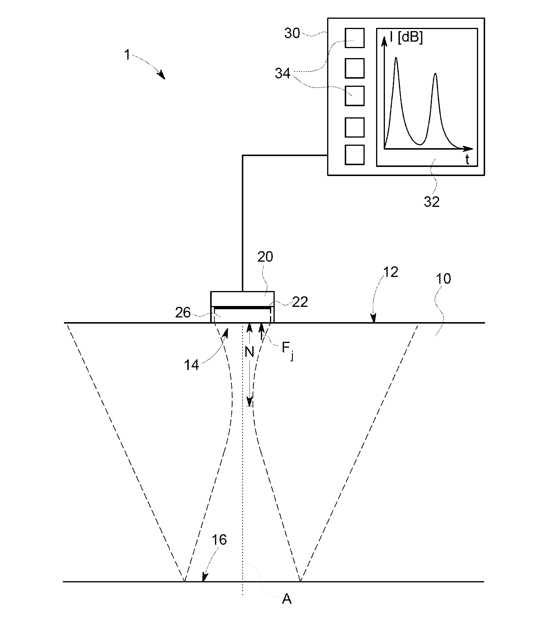
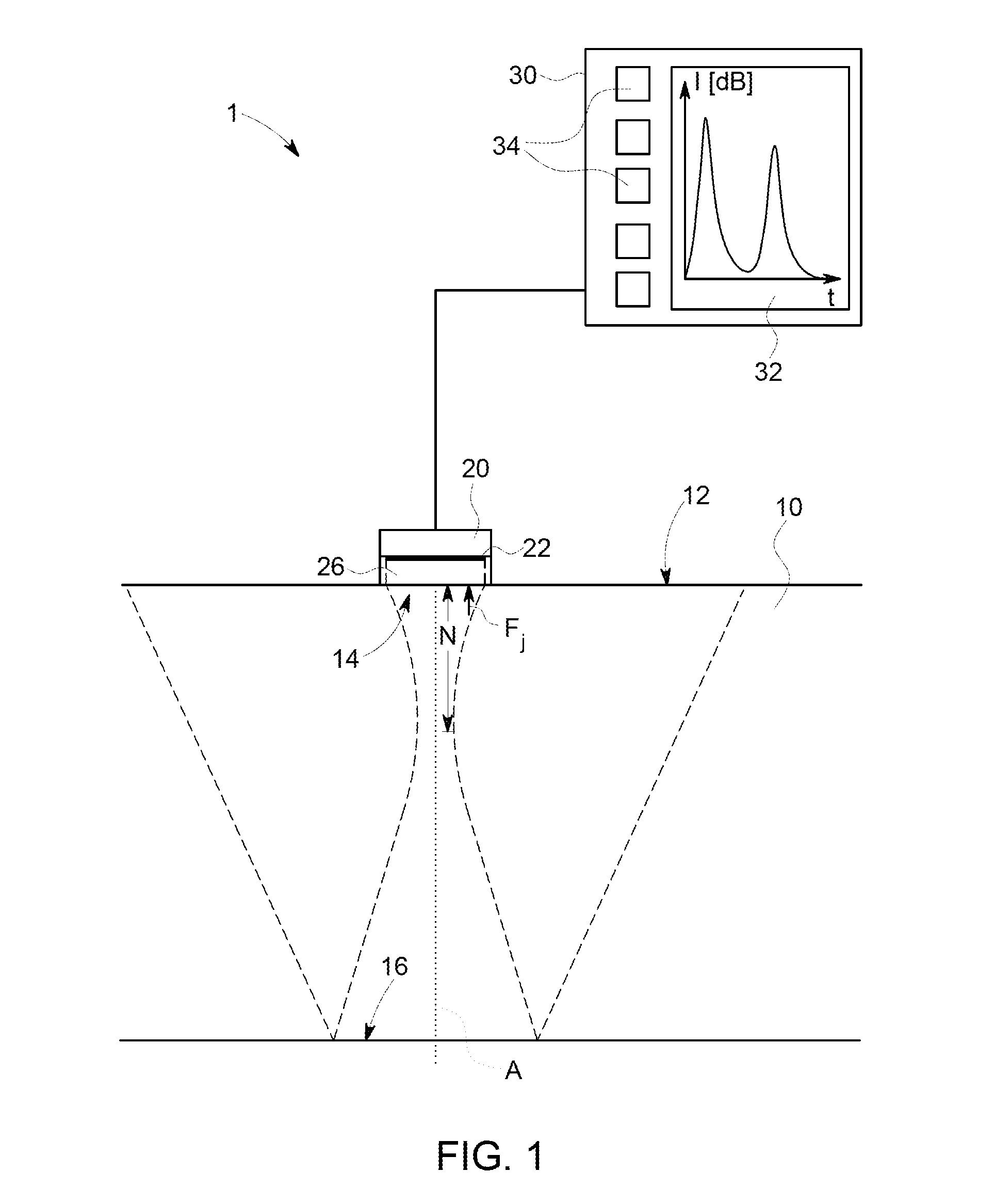
[0047]The device 1 shown schematically in FIG. 1 serves for the non-destructive inspection of a test object by means of ultrasound, wherein the test object 10 can have, in particular, a great material thickness S to be inspected. The device 1 comprises a control unit 30 which is electrically connected to an ultrasonic test probe 20. In turn, the ultrasonic test probe 20 comprises an ultrasonic transducer 22 disposed on a suitable leading body 26 which is provided to be placed upon a surface of the test object 10, which is hereinafter referred to as the coupling surface 12. The leading body 26 serves as a protection against wear and for acoustically coupling the ultrasonic transducer 22 to the test object 10; it can consist, for example, of Plexiglass®. In this case, the ultrasonic test probe 20 can be configured in such a way that it is manually guided by an examiner over the coupling surface 12 of the test object 10 so as to obtain information on structures in the material of the t...


PUM

PropertyMeasurementUnit
diameteraaaaaaaaaa
sound velocityaaaaaaaaaa
frequencyaaaaaaaaaa

Abstract

Method and apparatus for the non-destructive inspection of a test object with a large material thickness by means of ultrasound. The apparatus includes an ultrasonic test probe with an ultrasonic transducer divided into a plurality of individually activatable transducer segments wherein the transducer segments are concentric circles or rings, or sections thereof. A first group j (j=1, 2, 3, . . . ) of transducer segments is selected in such a way that a parallel activation of these transducer segments results in a circular active surface Fj of the ultrasonic transducer (22). An ultrasound inspection of the test object is undertaken with the first group j (j=1, 2, 3, . . . ) of transducer segments, wherein they are activated in parallel.

Description

FIELD AND BACKGROUND OF THE INVENTION[0001]The subject matter of the present invention is a method for the non-destructive inspection of a test object of great material thickness by means of ultrasound, the use of a test probe known per se for carrying out the method, an ultrasonic test probe particularly suitable for carrying out the method, a control unit for an ultrasonic test probe for the non-destructive inspection of a test object of great material thickness by means of ultrasound, which can, in particular, be configured for carrying out the method, and a device for the non-destructive inspection of a test object of great material thickness by means of ultrasound.[0002]A variety of methods for the non-destructive inspection of a test object by means of ultrasound are known from the field of material testing. In the pulse echo methods, a short ultrasonic pulse generated by an ultrasonic transducer acting as a transmitter is suitably insonified into a test object so that it prop...

Claims


Application Information

Patent Timeline
Patent Type & Authority Patents(United States)
IPC IPC(8): G01N29/00G01N29/26G01N29/44G01N29/34G01S15/89G01N29/22
CPCG01N29/262G01N29/4463G01N2291/02854G01N2291/106G01N29/221G01S15/8922
Inventor OBERDOERFER, YORK
Owner GE SENSING & INSPECTION TECH GMBH
Features
  • R&D
  • Intellectual Property
  • Life Sciences
  • Materials
  • Tech Scout
  • Unparalleled Data Quality
  • Higher Quality Content
  • 60% Fewer Hallucinations
Learn More