
Method and system for controlling traffic over a computer network

a technology of computer network and traffic control, applied in data switching networks, high-level techniques, sustainable buildings, etc., can solve the problem of selective placement of limits, and achieve the effect of not negatively affecting the performance of the host device, high throughput, and short tim

Active Publication Date: 2016-08-02
AVAGO TECH INT SALES PTE LTD
View PDF6 Cites 0 Cited by
  • Summary
  • Abstract
  • Description
  • Claims
  • Application Information

AI Technical Summary

Benefits of technology

This solution maintains high network throughput by minimizing packet drops and ensuring that only the responsible entities for congestion are rate limited, allowing other flows and servers to continue operating without interruption, thus optimizing network performance under congested conditions.

Problems solved by technology

In other words, limitations may be selectively placed, through software or firmware, on traffic for particular flows, virtual machines, and / or blade servers to accomplish network objectives under congested conditions.

Method used


Image

  • Method and system for controlling traffic over a computer network
  • Method and system for controlling traffic over a computer network
  • Method and system for controlling traffic over a computer network

Examples


Embodiment Construction

[0020]In the following description of preferred embodiments, reference is made to the accompanying drawings which form a part hereof, and in which it is shown by way of illustration specific embodiments in which the invention can be practiced. It is to be understood that other embodiments can be used and structural changes can be made without departing from the scope of the embodiments of this invention.

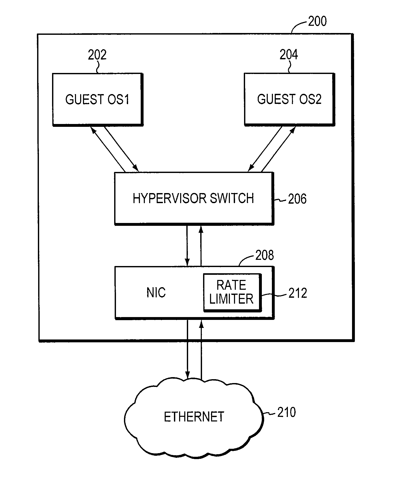
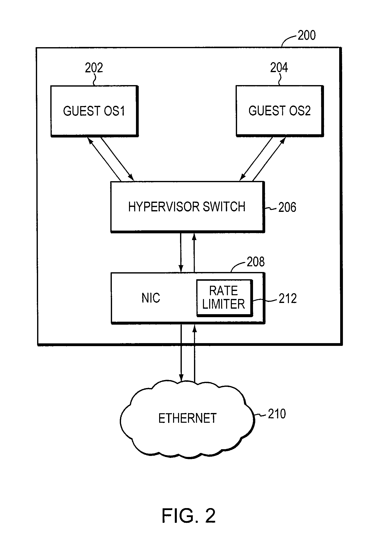
[0021]Although the idea of rate limiting packets issuing from a network port in response to congestion notification messages (e.g., BCN—backwards congestion notification) is well known, embodiments of the present invention disclose a distinct hardware-based rate limiter that can react to a BCN by loading (from firmware or software) rate allocations into profile table entries of registers in an application-specific integrated circuit (ASIC). The profile tables may also include entries loaded from hardware reflecting the current traffic rate in the network. The rate limiter may be embe...


PUM


Abstract

A rate limiter incorporated in a server connected to a network. The rate limiter is adapted to reduce congestion in the network in response to a congestion notification message. The server is adapted to send packets over the network. The rate limiter includes at least one of: a server rate limiter engine adapted to rate limit the packets in response to the server; a virtual machine rate limiter engine adapted to rate limit the packets in response to a virtual machine associated with the packets, the virtual machine hosted by the server; a flow rate limiter engine adapted to rate limit the packets in response to a flow associated with the packets; the flow being one of a plurality of flows transporting packets over the network; and a transmit engine adapted to rate limit the packets in response to a virtual pipe of the network for transmitting the packets.

Description

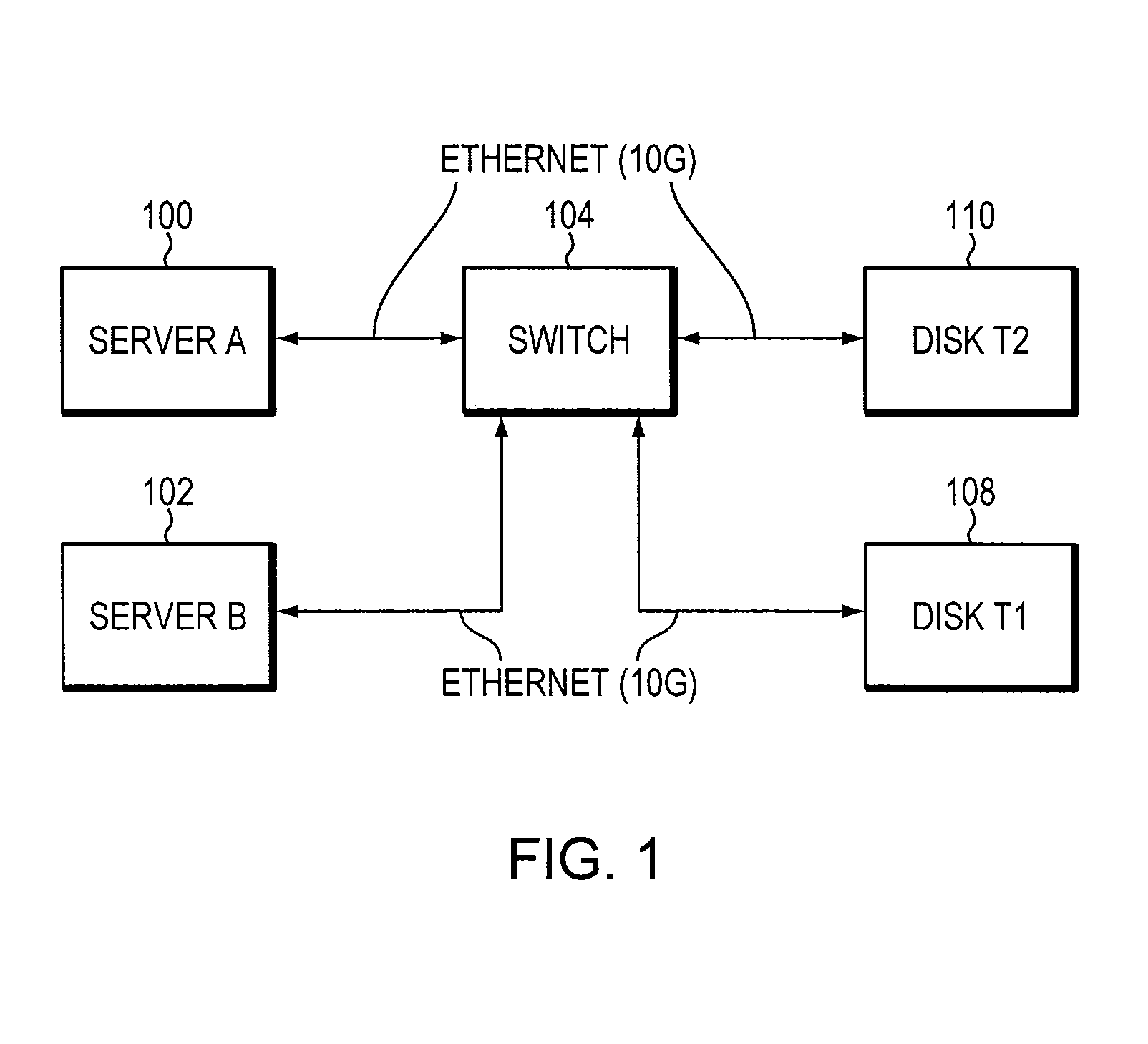
FIELD OF THE INVENTION[0001]This invention relates generally to traffic control in a computer network, and more specifically to rate limiting in response to congestion in the network.BACKGROUND OF THE INVENTION[0002]Network congestion can occur when too much data is sent through a particular link or node of a network. Such congestion may negatively affect the quality of service provided by the network. For example, it may cause queuing delays, packet losses, and blocked connections. Therefore, it is desirable to make sure that the amount of traffic passing through each node of the network does not exceed what the node can handle.[0003]A typical scenario of network congestion is illustrated in FIG. 1. As illustrated, the network includes two servers A and B 100, 102, a switch 104, and two disks T1 and T2108, 110. The number of devices shown in FIG. 1 is limited for illustration purposes only. Additional servers, switches, disks, and other types of devices may be connected to the netw...

Claims


Application Information

Patent Timeline
Patent Type & Authority Patents(United States)
IPC IPC(8): H04L12/801H04L12/851H04L12/825
CPCH04L47/10H04L47/11H04L47/2483H04L47/263Y02B60/31Y02D30/50
Inventor CHAVAN, MUKUND T.BHIDE, PARAGTUMULURI, CHAITANYASHENOY, RAVINDRA SADANAND
Owner AVAGO TECH INT SALES PTE LTD
Learn More