
Expandable intervertebral device, and systems and methods for inserting same

a technology of expandable implants and intervertebral fusion, which is applied in the field of expandable implantable devices for intervertebral fusion and/or immobilization, and systems and methods for inserting the same, can solve the problems of disc bulging or herniation, back pain, and impingement on the nerves of the spine, so as to improve reduce the lateral width of the intervertebral device, and reduce the back pain

Active Publication Date: 2016-08-09
XTANT MEDICAL HLDG INC
View PDF11 Cites 34 Cited by
  • Summary
  • Abstract
  • Description
  • Claims
  • Application Information

AI Technical Summary

Benefits of technology

The invention is a device that can be inserted between two vertebral bodies to promote bone growth and spine stability. It consists of two bearing or spacer members that can expand laterally to increase the stability of the spine. The device is designed to be easily inserted and expanded using a single tool. The expanded configuration increases the area in which osteoconductive material can be placed, promoting bone growth and fusion between the adjacent vertebral bodies.

Problems solved by technology

Typically, the patients' intervertebral discs, which support the spine, are damaged, causing the discs to bulge or herniate.
The disc bulge then impinges on the nerves of the spine and causes back pain.
However, the discectomy may structurally weaken the disc and often leads to subsequent structural failure of the disc due to wear and aging, once again causing impingement on the nerves of the spine and back pain.
One disadvantage of known laterally expandable IBDs is that the lateral size may be too large for insertion into the intervertebral disc space from a variety of surgical approaches, limiting the versatility of the IBD.
Such a side-by-side configuration is less advantageous or too large for some surgical approaches that have an especially narrow insertion opening.
Another perceived shortfall of known laterally expandable IBDs is maintaining the IBD in the desired expanded position.
Some known laterally expandable IBDs lack structure to keep the device from expanding further or retracting after being expanded initially by a surgeon.
A further disadvantage of known expandable IBDs is that it is difficult or impossible to insert bone graft material into or adjacent the expandable IBD after the IBD has been inserted into the intervertebral space.
While some expandable IBDs may be configured to hold bone graft material for promoting fusion, once the device is expanded, in some cases there may not be sufficient bone graft material to fill the bone graft cavity in the device such that sufficient bone graft material is kept in contact with the adjacent vertebral endplate to adequately promote bone ingrowth.

Method used


Image

  • Expandable intervertebral device, and systems and methods for inserting same
  • Expandable intervertebral device, and systems and methods for inserting same
  • Expandable intervertebral device, and systems and methods for inserting same

Examples


Embodiment Construction

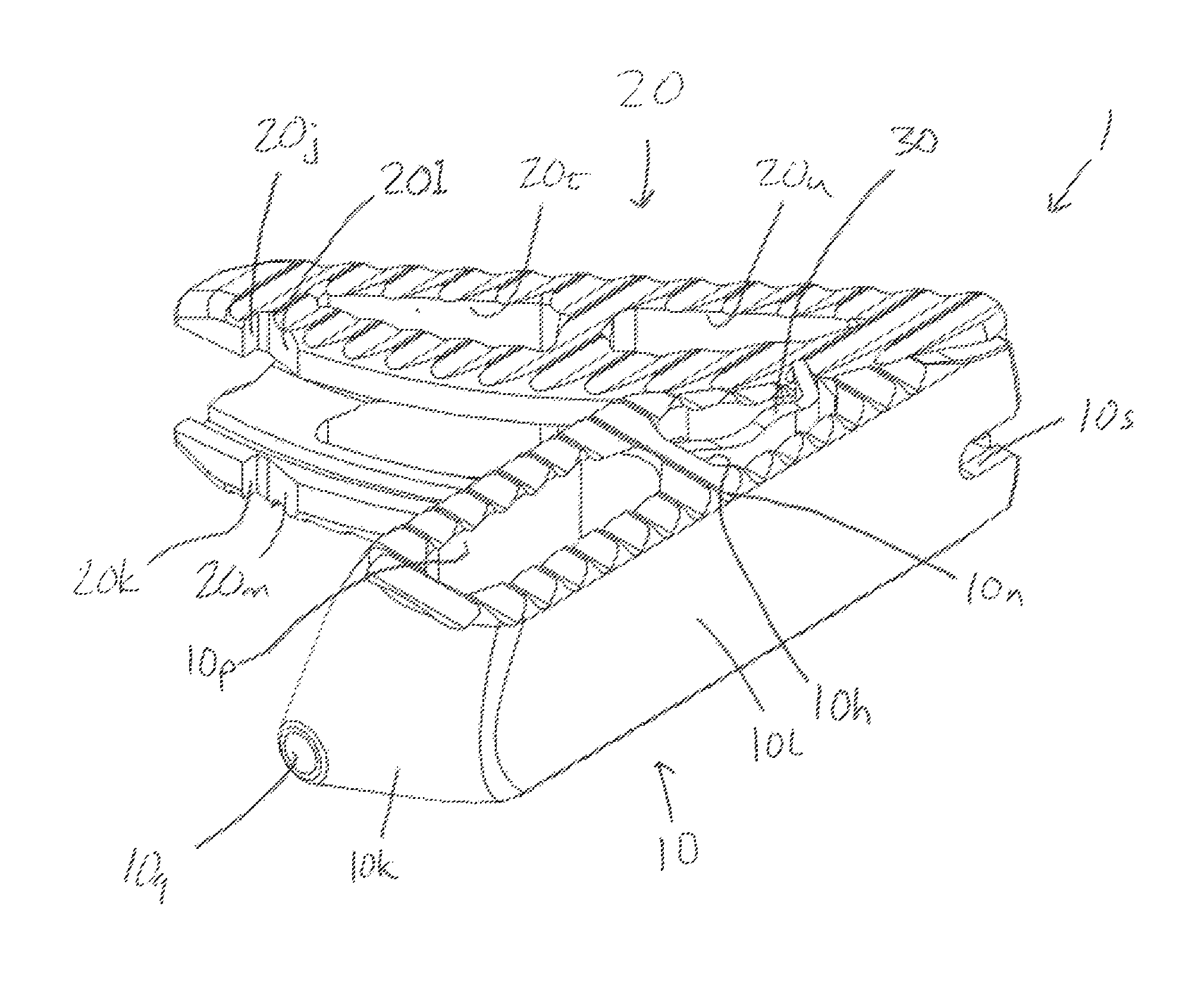
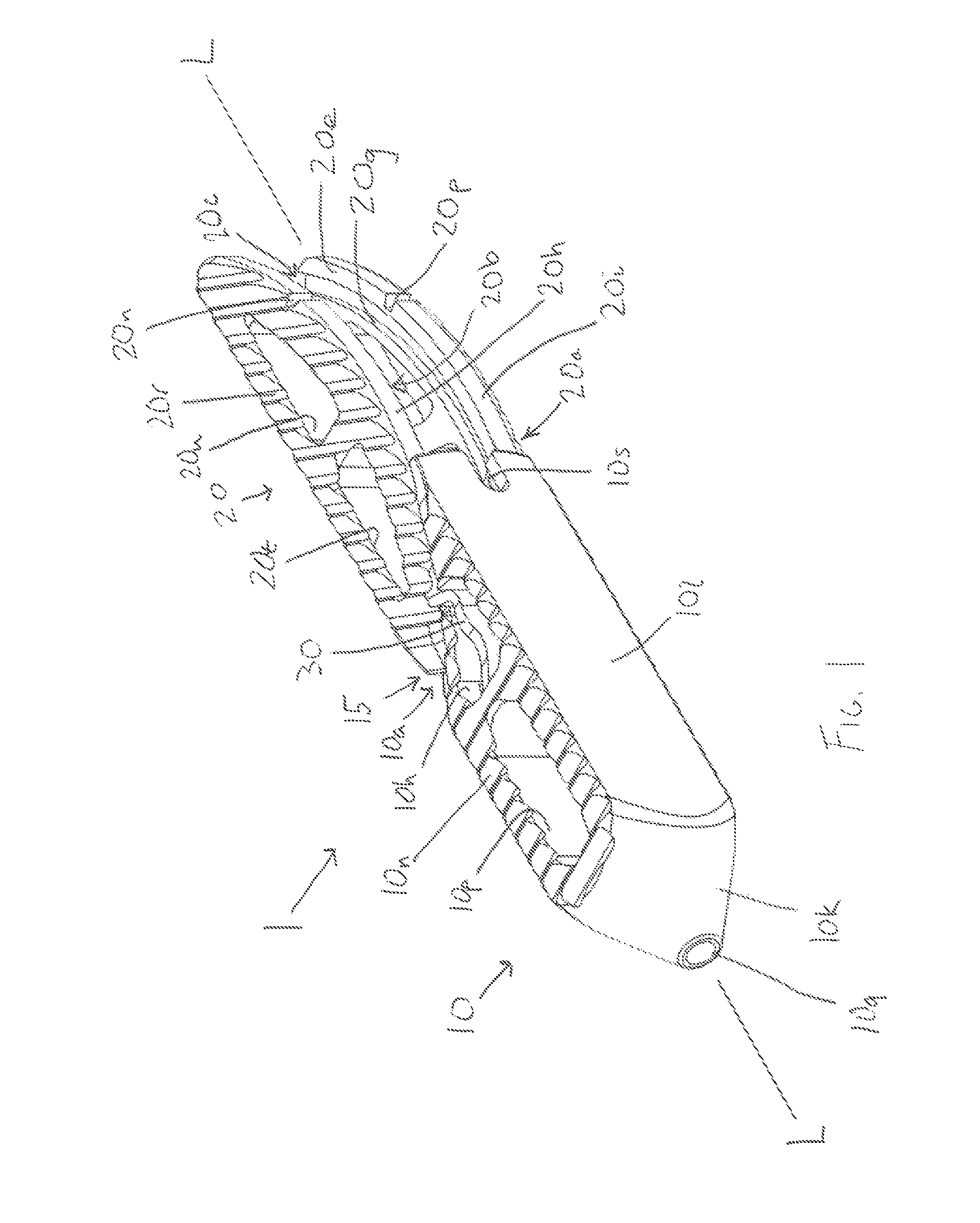
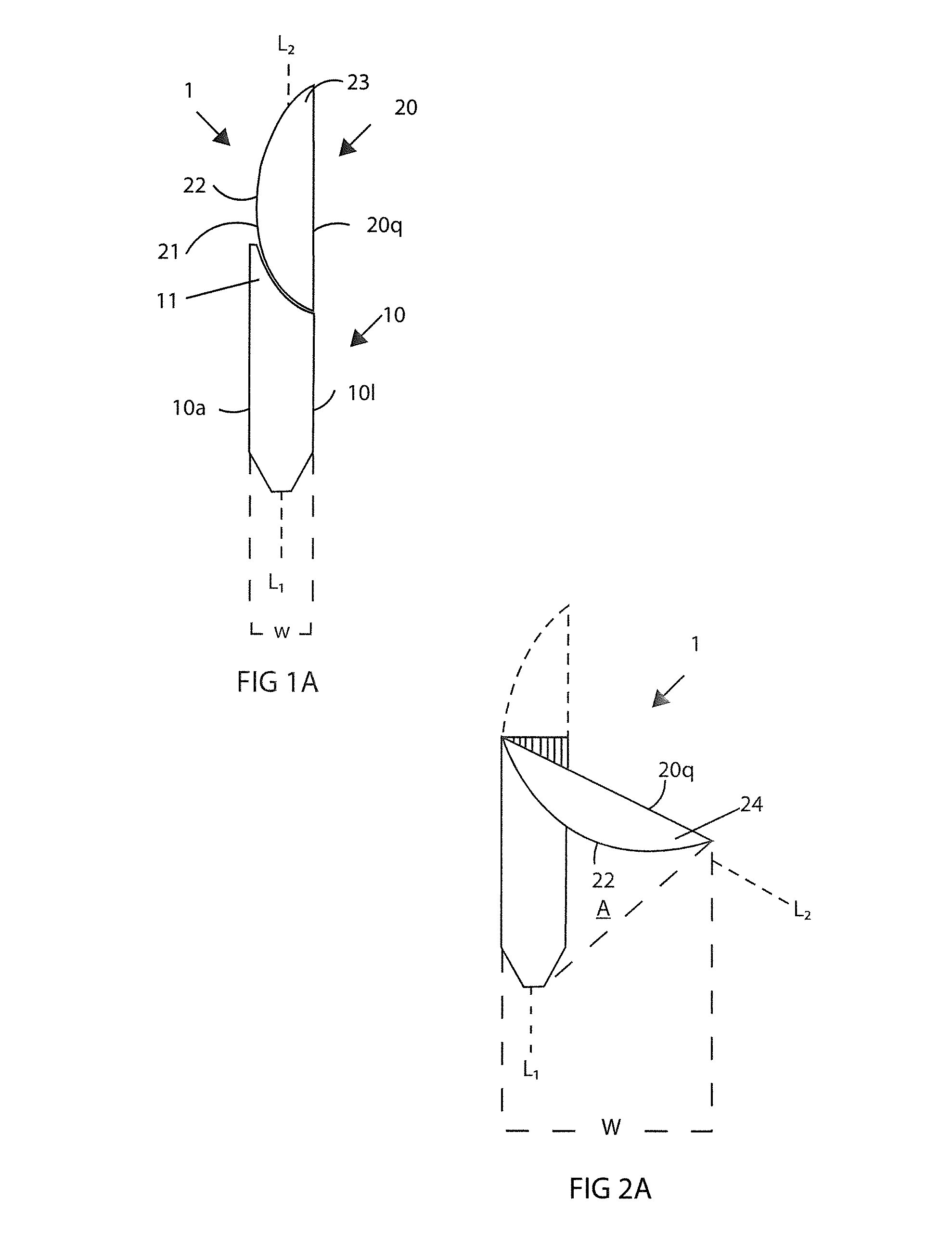
[0050]With reference to FIGS. 1-6 in accordance with one aspect of the invention, an expandable interbody device 1 has first and second bearing or spacer members 10, 20 configured to be implanted in the intervertebral space between adjacent vertebrae (FIGS. 11-13 and 19). The first and second spacer members are movably connected to one another via connecting portions 10a, 20a that form a sliding interface 15 between the spacer members 10, 20. The connecting portions 10a, 20a each have an arcuate configuration to allow the members to be cammingly shifted along an arcuate path with respect to one another. In this regard, the illustrated interface 15 is an arcuate, cam interface 15 comprised of mating cam surfaces and cam follower surfaces that permit the second bearing member 20 to be shifted from an aligned orientation shown in FIG. 1 to a laterally expanded orientation shown in FIG. 2 via a longitudinally directed force along the axis L applied to the trailing end portion 23 of the ...


PUM

PropertyMeasurementUnit
widthaaaaaaaaaa
widthaaaaaaaaaa
widthaaaaaaaaaa

Abstract

An expandable interbody device for implantation within an intervertebral space is provided, together with methods and tools for use therewith. The interbody devices include a leading first and trailing second bearing member configured to expand laterally via connecting portions disposed at the trailing end of the first being member and at least the leading end of the second bearing member. In some forms, the connecting portions have an arcuate configuration. The insertion tool is configured expand the interbody device by holding the first bearing member while shifting the second bearing member.

Description

CROSS-REFERENCE TO RELATED APPLICATION[0001]This application claims the benefit of U.S. Provisional Application No. 61 / 888,387, filed Oct. 8, 2013, which is hereby incorporated by reference in its entirety herein.FIELD OF THE INVENTION[0002]This invention pertains generally to implantable medical devices and, in particular, to expandable implantable devices for intervertebral fusion and / or immobilization and systems and methods for inserting the same.BACKGROUND OF THE INVENTION[0003]Many people develop back pain during the course of their life due to traumatic injury, disease, or genetic defect. Typically, the patients' intervertebral discs, which support the spine, are damaged, causing the discs to bulge or herniate. The disc bulge then impinges on the nerves of the spine and causes back pain. Surgeons often perform a discectomy to trim the disc bulge to alleviate back pain. However, the discectomy may structurally weaken the disc and often leads to subsequent structural failure of...

Claims


Application Information

Patent Timeline
Patent Type & Authority Patents(United States)
IPC IPC(8): A61F2/44A61F2/46A61F2/28A61F2/30
CPCA61F2/4455A61F2/442A61F2/4611A61F2/4465A61F2/447A61F2002/2835A61F2002/30383A61F2002/3039A61F2002/30401A61F2002/30403A61F2002/30481A61F2002/30484A61F2002/30538A61F2002/3055A61F2002/30629A61F2002/30632A61F2002/30774A61F2002/30825A61F2002/30827A61F2002/30828A61F2002/4475A61F2002/4622A61F2002/4623A61F2002/4629A61F2310/00796A61F2002/30482A61F2002/30624A61F2/4603A61F2002/30593
Inventor PERROW, SCOTT J.
Owner XTANT MEDICAL HLDG INC
Learn More