Gas turbine engine with integrated bottoming cycle system

a gas turbine engine and bottoming cycle technology, applied in the field of gas turbine engines, can solve the problems of low efficiency, low efficiency, and relatively high cost of steam-based rankine cycle systems, and achieve the effects of improving efficiency, improving efficiency, and improving efficiency

Inactive Publication Date: 2016-08-09
GENERAL ELECTRIC CO
View PDF45 Cites 9 Cited by
  • Summary
  • Abstract
  • Description
  • Claims
  • Application Information

AI Technical Summary

Problems solved by technology

Steam-based Rankine cycle systems, however, may be relatively costly and inefficient, particularly when operating on low temperature waste heat.
Similarly, the performance of an organic Rankine cycle system may be limited by the nature of the working fluid therein.

Method used


Image

  • Gas turbine engine with integrated bottoming cycle system
  • Gas turbine engine with integrated bottoming cycle system
  • Gas turbine engine with integrated bottoming cycle system

Examples


Embodiment Construction

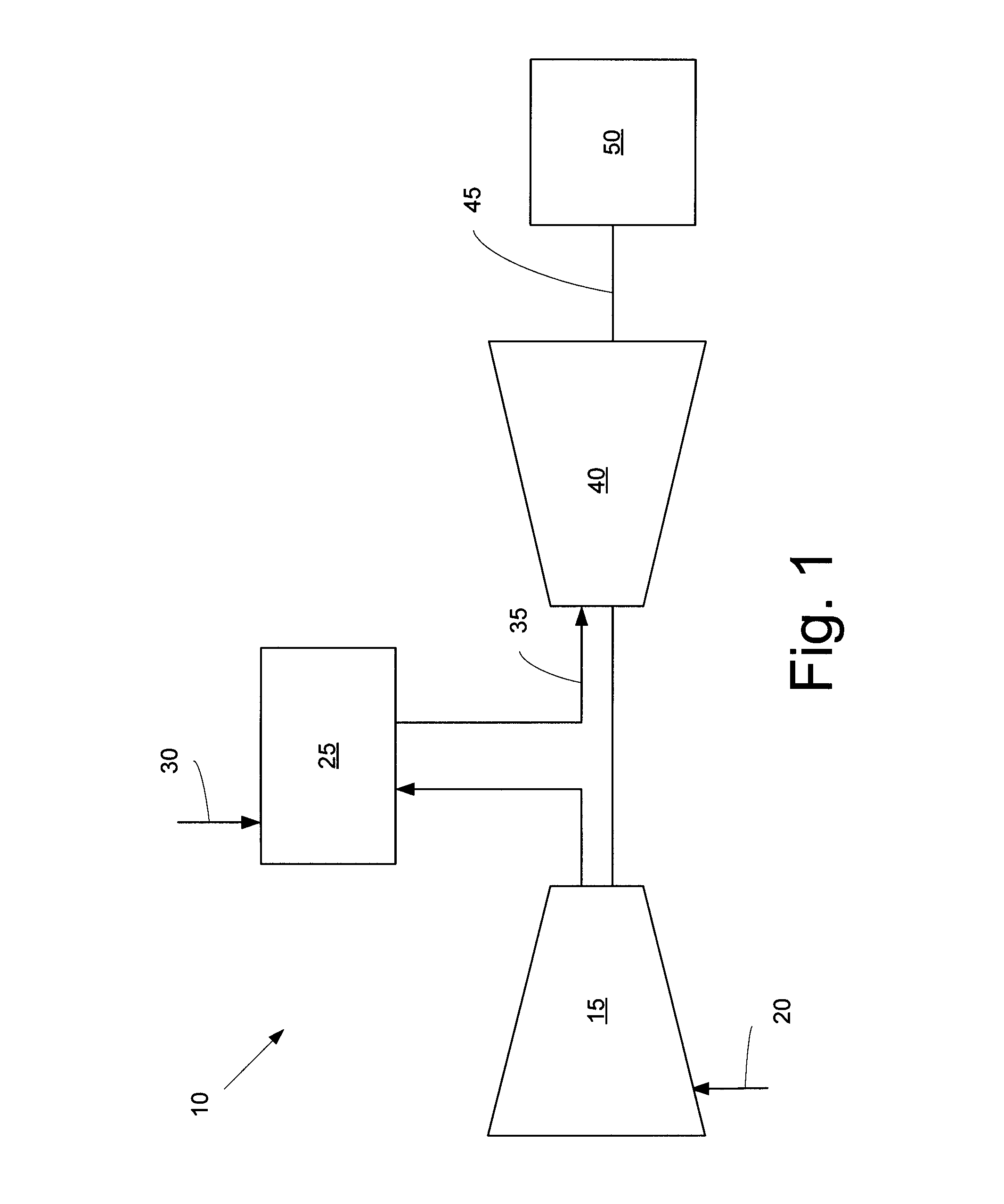
[0010]Referring now to the drawings, in which like numerals refer to like elements throughout the several views, FIG. 1 shows a schematic view of gas turbine engine 10 as may be used herein. The gas turbine engine 10 may include a compressor 15. The compressor 15 compresses an incoming flow of air 20. The compressor 15 delivers the compressed flow of air 20 to a combustor 25. The combustor 25 mixes the compressed flow of air 20 with a pressurized flow of fuel 30 and ignites the mixture to create a flow of combustion gases 35. Although only a single combustor 25 is shown, the gas turbine engine 10 may include any number of combustors 25. The flow of combustion gases 35 is in turn delivered to a turbine 40. The flow of combustion gases 35 drives the turbine 40 so as to produce mechanical work. The mechanical work produced in the turbine 40 drives the compressor 15 via a shaft 45 and an external load 50 such as an electrical generator and the like. A flow of hot exhaust gases 55 exits ...


PUM


Abstract

The present application provides an integrated bottoming cycle system for use with a gas turbine engine. The integrated bottoming cycle system described herein may include a compressor / pump, a cooling circuit downstream of the compressor / pump, a bottoming cycle heat exchanger, a heating circuit downstream of the bottoming cycle heat exchanger, and a number of turbine components in communication with the cooling circuit and / or the heating circuit to maximize the overall plant efficiency and economics.

Description

TECHNICAL FIELD[0001]The present application and the resultant patent relate generally to gas turbine engines and more particularly relate to a gas turbine engine with an integrated supercritical carbon dioxide bottoming cycle system for electric power production and efficient heating and cooling of any number of different turbine components.BACKGROUND OF THE INVENTION[0002]The overall efficiency of a power plant improves with the effective use of the waste heat produced therein. The term “waste heat” generally may encompass any supply of residual heat produced by a primary process that is not conventionally exploited as a source of energy. One method of using the waste heat produced by a combustion engine is to apply a bottoming Rankine cycle so as to generate electricity. Steam-based Rankine cycle systems, however, may be relatively costly and inefficient, particularly when operating on low temperature waste heat. Similarly, the performance of an organic Rankine cycle system may b...

Claims


Application Information

Patent Timeline
Patent Type & Authority Patents(United States)
IPC IPC(8): F01K23/10
CPCF01K23/10F01K23/103Y02E20/16F02C1/007F02C6/18F02C7/10F02C7/224
Inventor LAING, DONALD GORDONBOOTH, CHARLES MICHAEL
Owner GENERAL ELECTRIC CO
Why Eureka
Try Eureka