
Wire harness

a wire harness and wire technology, applied in the direction of insulated conductors, cables, electric/fluid circuits, etc., can solve the problems of insufficient heat dissipation effect, insufficient heat generation at the conducting path, and small part of the conducting path that is in contact with the inner surface of the exterior member, so as to improve the heat dissipation effect, reduce the susceptibility to heat from the outside, and increase the occupancy of the conducting path

Active Publication Date: 2016-08-09
YAZAKI CORP
View PDF13 Cites 5 Cited by
  • Summary
  • Abstract
  • Description
  • Claims
  • Application Information

AI Technical Summary

Benefits of technology

[0016]The wire harness of the above (1) has the shape changed portion at least on a part of the exterior member, and the shape changed portion includes the small tube portion, the tube continuous portion and the large tube portion. For this reason, the occupancy of the conducting path can be increased in the small tube portion. As a consequence, heat generated at the conducting path is efficiently absorbed at the small tube portion, so that the absorbed heat can be dissipated from the small tube portion. Consequently, the heat dissipation effect can be enhanced compared with the conventional one.
[0017]Moreover, according to the wire harness of the above (1), since the exterior member has the shape changed portion including the small tube portion, the tube continuous portion and the large tube portion, the distance between the exterior member and the heat generation source can be secured by disposing the small tube portion of the shape changed portion in accordance with the heat generation source, so that the susceptibility to heat from the outside can be reduced.
[0018]According to the wire harness of the above (2), in addition to the advantage of the above (1), the following advantage is produced: By reducing the outer periphery length of the small tube portion, the surface area of the small tube portion can be made smaller than that of the large tube portion, and the surface area can be made small compared with when extrusion is performed. Consequently, since the heat generation source is handled at the small tube portion having such a small surface area, the susceptibility to heat from the outside can be reduced.
[0019]According to the wire harness of the above (3), in addition to the advantage of the above (1) or (2), the following advantage is produced: The wire harness can be formed of an exterior member making use of the characteristics of the resin.
[0020]According to the wire harness of the above (4), in addition to the advantage of the above (1) or (2), the following advantage is produced: The wire harness can be formed of an exterior member making use of the characteristics of the metal.

Problems solved by technology

The above-described conventional art has several problems related to heat as follows: When the occupancy of the conducting path in the exterior member is low, the part of the conducting path that is in contact with the inner surface of the exterior member is small.
At the part where the conducting path and the inner surface of the exterior member are not in contact with each other, the distance of the conducting path from the inner surface of the exterior member is large, so that heat generated at the conducting path cannot be effectively transmitted to the exterior member.
From these, with the conventional art, heat dissipation effect cannot be sufficiently obtained.
In these cases, since the exterior member covering the part is directly exposed to the heat from the heat generation source, there is a possibility that the conducting path accommodated in the exterior path is affected.

Method used


Image

  • Wire harness
  • Wire harness
  • Wire harness

Examples


first embodiment

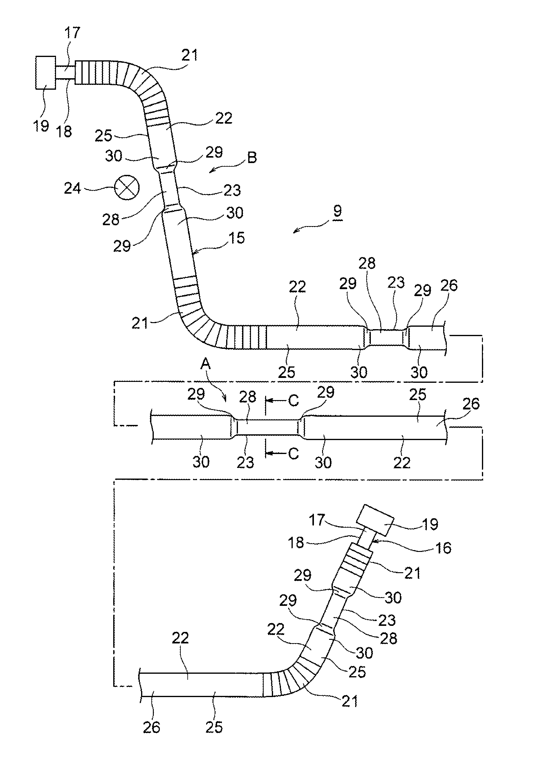
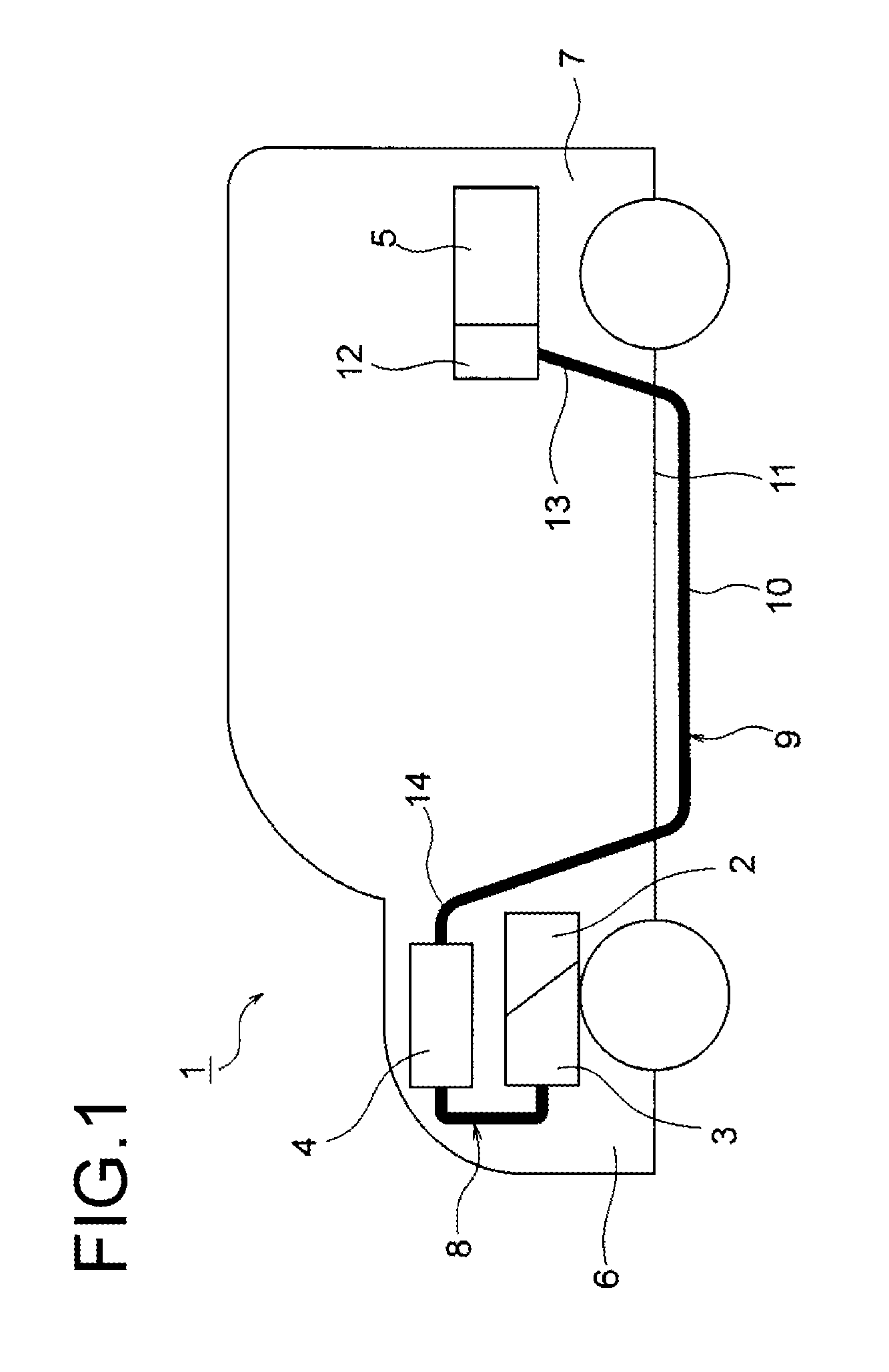
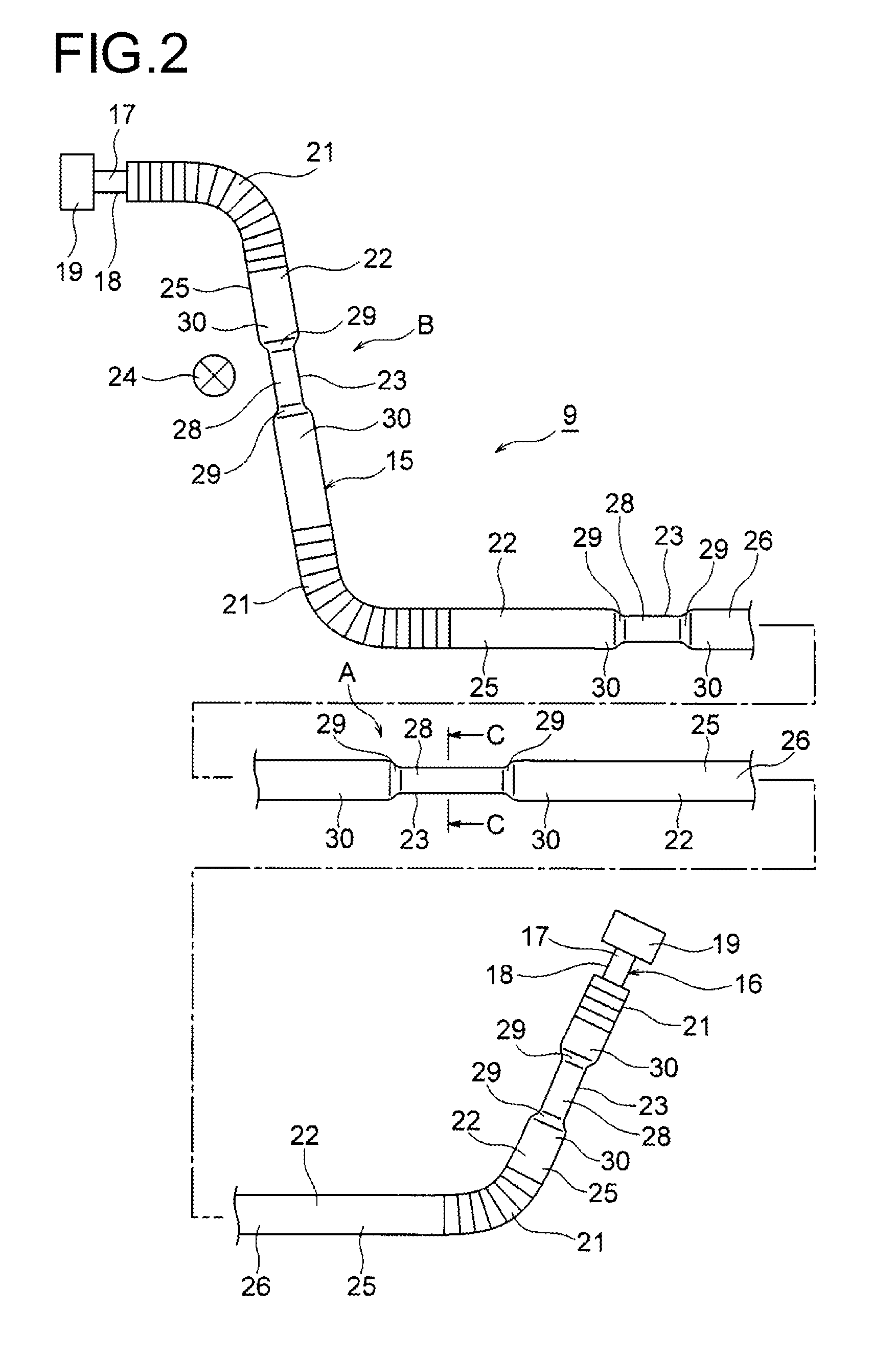
[0030]Hereinafter, a first embodiment will be described with reference to FIGS. 1 to 5. FIG. 1 is a schematic view showing a cabling condition of a wire harness according to the first embodiment. FIG. 2 is a structural view of the wire harness of FIG. 1, FIG. 3 is a longitudinal cross-sectional view of the part of the arrow A of FIG. 2, FIG. 4 is an enlarged view of the part of the arrow B of FIG. 2, and FIG. 5 is a cross-sectional view taken on line C-C of FIG. 2 and FIG. 3.

[0031]In the first embodiment, description will be given with an example where the present invention is adopted for wire harnesses cabled to a hybrid car (this may be an electric car or a general car).

[0032]In FIG. 1, reference designation 1 represents a hybrid car. The hybrid car 1 is a vehicle driven by a mixture of two powers of an engine 2 and a motor unit 3. The motor unit 3 is supplied with the power from a battery 5 (in other words, a battery pack) through an inverter unit 4. The engine 2, the motor unit ...

second embodiment

[0071]Hereinafter, a second embodiment will be described with reference to FIG. 6. FIG. 6 is a cross-sectional view of a wire harness according to the second embodiment. Elements basically the same as those of the above-described first embodiment are denoted by the same reference designations and detailed descriptions thereof are omitted. Moreover, the wire harness of the second embodiment is cabled for use similarly to the wire harness of the first embodiment.

[0072]In FIG. 6, the wire harness 9 includes an exterior member 15 that is oval in cross section and a high voltage conducting path 51 (that is, the conducting path) protected by being covered with the exterior member 15. A detailed description of the exterior member 15 of the second embodiment is omitted here since it is different from that of the first embodiment only in the cross-sectional shape (that is, the cross-sectional shape is formed in accordance with the high voltage conducting path 51).

[0073]The high voltage condu...

third embodiment

[0082]Hereinafter, a third embodiment will be described with reference to FIG. 7. FIG. 7 is a cross-sectional view of an exterior member as another example. Elements basically the same as those of the above-described first embodiment are denoted by the same reference designations and detailed descriptions thereof are omitted. Moreover, the wire harness of the third embodiment is cabled for use similarly to the wire harness of the first embodiment.

[0083]In FIG. 7, the wire harness 9 includes an exterior member 15 having a shape changed portion 61 in at least one position and a high voltage conducting path 16 (that is, the conducting path) protected by being covered with the exterior member 15.

[0084]The shape changed portion 61 is formed as a portion where the size of the length of the outer periphery of the exterior member 15 is changed, or a portion that is large and small in diameter. Since formed as such a portion, the shape changed portion 61 has at least one small tube portion 6...


PUM

PropertyMeasurementUnit
conductingaaaaaaaaaa
shapeaaaaaaaaaa
outer shapeaaaaaaaaaa

Abstract

A wire harness includes at least one conducting path, and a tubular exterior member that covers the conducting path. The exterior member has a shape changed portion in at least one position. The shape changed portion includes at least one small tube portion which includes an accommodation space necessary for accommodating the conducting path, a tube continuous portion one end of which is continuous with an end of the small tube portion, and a large tube portion which is continuous with another end of the tube continuous portion and includes a tubular shape that is larger in outer shape than the small tube portion.

Description

CROSS REFERENCE TO RELATED APPLICATION[0001]This application is a continuation of PCT application No. PCT / JP2013 / 073441, which was filed on Aug. 30, 2013 based on Japanese Patent Application (No. 2012-192779) filed on Sep. 3, 2012, the contents of which are incorporated herein by reference. Also, all the references cited herein are incorporated as a whole.BACKGROUND[0002]1. Technical Field[0003]The present invention relates to a wire harness including at least one conducting path and a tubular exterior member covering the conducting path.[0004]2. Background Art[0005]Generally, the battery and the inverter unit of a hybrid car and an electric car are electrically connected by a high voltage (that is, high electric voltage) wire harness. The wire harness disclosed in JP-A-2004-224156 shown below includes a high voltage electric wire serving as a high voltage conducting path and an exterior member accommodating the high voltage electric wire.[0006]The above-described conventional art h...

Claims


Application Information

Patent Timeline
Patent Type & Authority Patents(United States)
IPC IPC(8): H01B7/00H02G3/04B60R16/02H01B7/17
CPCB60R16/0215H02G3/0481H02G3/0487H01B7/0045H01B7/17
Inventor INAO, SHINICHIADACHI, HIDEOMIOGUE, TAKESHIOGA, TATSUYASUGURO, MASAAKIOZAKI, YOSHIAKIYOSHIDA, HIROYUKI
Owner YAZAKI CORP
Learn More