Low Leakage Electrolytic Capacitors

An electrolytic capacitor, low leakage technology, applied in the direction of electrolytic capacitors, capacitors, capacitor parts, etc., can solve the problems of dielectric film damage, low equivalent series resistance, leakage current increase, etc., to increase conductivity, improve Conductivity, the effect of increasing the conduction path

Active Publication Date: 2020-09-08
APAQ TECH
View PDF7 Cites 0 Cited by
  • Summary
  • Abstract
  • Description
  • Claims
  • Application Information

AI Technical Summary

Problems solved by technology

[0003] According to different electrolytes, capacitors are divided into liquid electrolytic capacitors using fluid electrolytes (such as electrolyte) and solid electrolytic capacitors using solid electrolytes (such as conductive polymers). Compared with liquid capacitors, solid electrolytic capacitors have a lower Effective Series Resistance (Equivalent Series Resistance; ESR), however, the conductive solid layer included in the solid electrolytic capacitor cannot be uniformly and tightly covered on the surface of the sponge-like anode foil, and it is prone to peeling off; in addition, in order to reduce ESR, the conductive solid layer is usually Therefore, repeated oxidative polymerization is required in actual manufacturing, so as to cause damage to the dielectric film. Since the solid electrolytic capacitor lacks a repair mechanism for the damage, the leakage current may increase. In the worst case There is a possibility of a short circuit in the case of

Method used


Image

  • Low Leakage Electrolytic Capacitors
  • Low Leakage Electrolytic Capacitors
  • Low Leakage Electrolytic Capacitors

Examples


no. 1 example

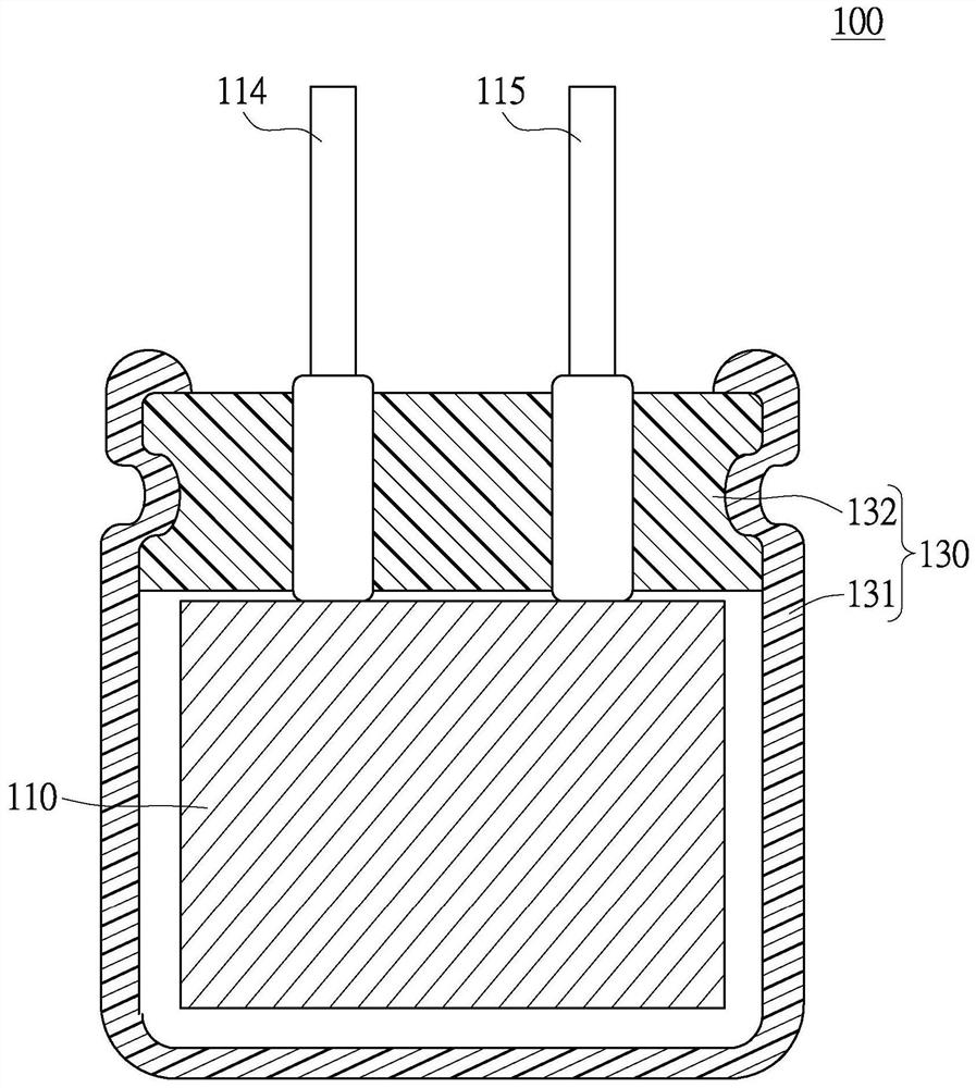
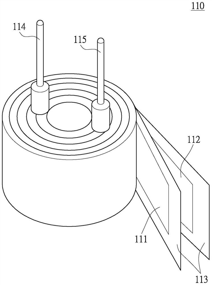
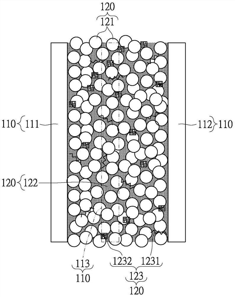
[0038] Please also refer to figure 1 and figure 2 , figure 1 is a cross-sectional view of a low-leakage electrolytic capacitor according to the first embodiment of the present invention, figure 2It is a cross-sectional view of the wound capacitor assembly of the low leakage electrolytic capacitor. As shown in the figure, this embodiment provides a low-leakage wound electrolytic capacitor 100, which mainly includes a wound capacitor assembly 110, a hybrid conductive medium 120, and a package body 130. The wound capacitor assembly 110 The main body is wound by an anode foil 111, a cathode foil 112 and a separator 113 arranged between the anode foil 111 and the cathode foil 112, and the hybrid conductive medium 120 is impregnated in the wound capacitor assembly 110, The packaging body 130 is used to completely cover the wound capacitor assembly 110 and the hybrid conductive medium 120 .

[0039] Specifically, an anode guide pin 114 is installed on the anode foil 111, and a ...

no. 2 example

[0066] Please refer to Figure 4 , is a schematic diagram of a low-leakage electrolytic capacitor according to the second embodiment of the present invention. As shown in the figure, this embodiment provides a low-leakage chip-type electrolytic capacitor 200, which mainly includes a base material layer 210, an annular insulating layer 220 and a conductive layer 230, and the annular insulating layer 220 surrounds the base material layer. 210 , thereby defining an anode portion 211 and a cathode portion 212 on the substrate layer 210 , and the conductive layer 230 covers the surface of the cathode portion 212 .

[0067] Specifically, the material of the substrate layer 210 can be a valve function metal (such as aluminum, tantalum, niobium, titanium, etc.). The surface of the anode part 211 and the surface of the cathode part 212 is roughened by etching, and a dielectric film (not shown) is formed on the surface of the anode part 211 and the surface of the cathode part 212 by ch...


PUM

PropertyMeasurementUnit
thicknessaaaaaaaaaa

Abstract

The invention discloses a low-electric leakage electrolytic capacitor. The capacitor comprises a wound type capacitor assembly, a mixed type conductive medium and a packaging body; an anode foil, a cathode foil and an isolating membrane between the anode foil and the cathode foil are wound so as to form the wound type capacitor assembly; the mixed type conductive medium is impregnated in the woundtype capacitor assembly; the mixed conductive medium contains a conductive polymer and an ionic liquid; and the packaging body completely wraps the wound type capacitor assembly and the mixed type conductive medium. The low-electric leakage electrolytic capacitor of the invention has the superior characteristics of a solid-state low-electric leakage electrolytic capacitor and can alleviate an electric leakage condition.

Description

technical field [0001] The invention relates to an electrolytic capacitor, in particular to a low-leakage electrolytic capacitor which combines the excellent characteristics of a solid electrolytic capacitor and a liquid electrolytic capacitor. Background technique [0002] As we all know, the basic function of a capacitor is to charge and discharge, and the electrical functions derived from it, such as bypass, coupling, filtering, oscillation, phase shift, etc., make capacitors become consumer appliances, computer motherboards and peripherals, and power supplies. One of the indispensable components in the electronic circuits of communication products and automotive electronic products. [0003] According to different electrolytes, capacitors are divided into liquid electrolytic capacitors using fluid electrolytes (such as electrolyte) and solid electrolytic capacitors using solid electrolytes (such as conductive polymers). Compared with liquid capacitors, solid electrolytic...

Claims


Application Information

Patent Timeline
Patent Type & Authority Patents(China)
IPC IPC(8): H01G9/022H01G9/028H01G9/035H01G9/14
CPCH01G9/022H01G9/028H01G9/035H01G9/14
Inventor 陈明宗苏忠瑞
Owner APAQ TECH
Why Eureka
Try Eureka